I sifted through a Nick Sukhov project here on diyaudio. Lots of discussion. That reminded me I was intrigued by the Kaneda but had a hard time finding the transistors and lost interest.
I could probably house the OREAD PCBs (minus the PSU) inside my turntable.
Would it be an option to add an opamp follower (eg LME49720) inside the turntable just to reduce the cable capacitance? One could compare it to a phantom-fed microphone.
I could probably house the OREAD PCBs (minus the PSU) inside my turntable.
Would it be an option to add an opamp follower (eg LME49720) inside the turntable just to reduce the cable capacitance? One could compare it to a phantom-fed microphone.
I would shorten the connecting cable to 0.5m.
In principle, you can connect a simple FET buffer (or linear Amp-Stage) to the end of the tonearm tube, or of course the bearing ... and also feed it phantom. However, I wouldn't do that - the drive is the drive and nothing more.
A small, flat housing for the EQ, the power supply unit separate and far away ... Buffer in front of each input of the Najda DSP multiplexer - finished.
kindly,
HBt.
I would recommend Blue Jeans cable if you want to replace the cable. They actually list the specs for their cable and us Belden cable. https://www.bluejeanscable.com/index.htm
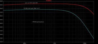
Earlier in the thread we found that the input capacitance of the OREAD is max. 75pF; without an additional capacitor CI connected in parallel.
Together with a standard cable with a capacitance of approx. 200pF/m, even an AT pickup is still fine if the cable is short enough, e.g. 50cm.
I have a ~1.2m connection cable with 210pF, no capacitor CI connected and an additional input resistor RI=560k connected for an Ortofon OM10.
But if I connect an AT pickup instead without any further changes (SME headshell, AT72), I cannot detect any significant change in the sound.
The same goes for a DUAL TKS236.
I think you don't have to take it all so seriously if the capacitance values stay within reasonable limits
Good You mention this, I started with the obligatory 47k but read elsewhere one can go considerably higher, ie 500kinput resistor RI=560k
Ah. Something I have gotten wrong then. I see 1/ (1/50 + 1/560) is about 46 in total. Thanks for pointing this out. (I didn't get very far with the enclosure last weekend and this is a working week. My build is all in pieces for a while now)RI=47K the pickup sees around 25k
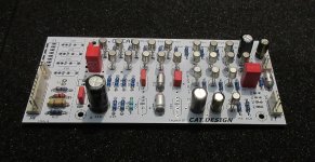
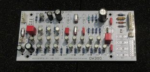
I got the new OREAD PCBs, version r06, and immediately assembled one.


This time, as already announced, the 'NPN circuit', i.e. with NPN transistors at the input.
All other transistors, electrolytic capacitors and of course the operating voltages have their polarity swapped accordingly.
To do this, I made a few small changes to the board layout compared to version r04.
To avoid the operating voltage having to be connected the other way round than the board print indicates depending on the selected circuit (NPN/PNP), the polarity of the operating voltages on the new board r06 is determined by wire bridges P1/P2 and N1/N2, but the external connection to the power supply remains as before.
The polarity of electrolytic capacitors is also marked by a dot in the assembly print.
There is also now a separate place and print for the resistor RB.

PNP circuit:
Wire bridges P1, P2
Transistors T1, T2, T5, T7 = PNP
Transistors T3, T4, T6 = NPN
Capacitor connection: dot = negative
NPN circuit:
Wire bridges N1, N2
Transistors T1, T2, T5, T7 = NPN
Transistors T3, T4, T6 = PNP
Capacitor connection: dot = positive
I used the transistors BC107B (NPN) and BC177B (PNP) in the NPN circuit because I have a lot of them; I kept all other component values.
Thanks to the modified design of the circuit board described, I was able to swap it - even with the NPN circuit - for one of the two (stereo) PNP circuit boards (r04) in my phono preamplifier simply by plugging it in. It worked straight away without any problems and there was no difference between the two channels when I first listened to it briefly.
There is also no difference in terms of noise. You only hear a very quiet hissing sound when the volume control is turned up all the way, the same for both versions.


This time, as already announced, the 'NPN circuit', i.e. with NPN transistors at the input.
All other transistors, electrolytic capacitors and of course the operating voltages have their polarity swapped accordingly.
To do this, I made a few small changes to the board layout compared to version r04.
To avoid the operating voltage having to be connected the other way round than the board print indicates depending on the selected circuit (NPN/PNP), the polarity of the operating voltages on the new board r06 is determined by wire bridges P1/P2 and N1/N2, but the external connection to the power supply remains as before.
The polarity of electrolytic capacitors is also marked by a dot in the assembly print.
There is also now a separate place and print for the resistor RB.

PNP circuit:
Wire bridges P1, P2
Transistors T1, T2, T5, T7 = PNP
Transistors T3, T4, T6 = NPN
Capacitor connection: dot = negative
NPN circuit:
Wire bridges N1, N2
Transistors T1, T2, T5, T7 = NPN
Transistors T3, T4, T6 = PNP
Capacitor connection: dot = positive
I used the transistors BC107B (NPN) and BC177B (PNP) in the NPN circuit because I have a lot of them; I kept all other component values.
Thanks to the modified design of the circuit board described, I was able to swap it - even with the NPN circuit - for one of the two (stereo) PNP circuit boards (r04) in my phono preamplifier simply by plugging it in. It worked straight away without any problems and there was no difference between the two channels when I first listened to it briefly.
There is also no difference in terms of noise. You only hear a very quiet hissing sound when the volume control is turned up all the way, the same for both versions.
All variants of the OREAD idea can be implemented with the current board
For me, this means that the OREAD chapter has moved beyond the prototype status - and we could be approaching the project supra2024 in the foreseeable future, which would ultimately be a fork in the road that the initial discussion thread had also taken.
But for now, the flood of OREAD replicas should slowly come in and enrich other continents. At the end of the day, you only need one EQ in life, and with OREAD you are already very close to the ideal.
thx catd
Greetings,
HBt.
for now
supra 2024
I am very curious to see whether the symmetrical core (which I call SUPRA2024) will also be a success.
Symm in the sense of: between the RAils.
supra 2024
I am very curious to see whether the symmetrical core (which I call SUPRA2024) will also be a success.
Symm in the sense of: between the RAils.
I should have known. I also have a few bc107b's 🙂 (But maybe only one bc177) The cards look great. You should strip the black plastic covers off the electrolytic's. And have a glass cover on the box. I need to get my box built. Work is pitifully prioritized.I used the transistors BC107B (NPN) and BC177B (PNP) in the NPN circuit because I have a lot of them
? You mean for optical reasons? So that these components also have a metallic shine and match the metal can transistors? Ok, one could take a look at what it looks like under the cover.You should strip the black plastic covers off the electrolytic's
One would then also have to replace the red capacitors with ones that match the metallic look better, perhaps light blue. OK, now it might be getting a little bit decadent... 😀
This morning I received a new needle (Analogis Black Diamond) for my Ortofon OM in the mail. I'm going to play several LPs now...
I bet
you end up liking the NPN-PNP-NPN overkill version of the OREAD the best of all four options.
Have fun listening to the LP while (hopefully the last) another heatwave from climate hell descends on us all.
kindly,
HBt.
😉
you end up liking the NPN-PNP-NPN overkill version of the OREAD the best of all four options.
Have fun listening to the LP while (hopefully the last) another heatwave from climate hell descends on us all.
kindly,
HBt.
😉
So far I have not been able to detect any audible difference between the versions (PNP/NPN, with +/- supply).
If you have golden ears and can hear the fleas coughing, you might experience it differently.
What is 'measurable', however:
When looking through the data sheets, you will notice that the PNP transistors have stated higher capacitance than the NPN, about twice as much.
This is correctly taken into account in the LTspice models BC550/560/107/177.
When simulating the NPN circuit, the input capacitance shown is therefore about half that of the PNP circuit.
Input capacitance of the NPN circuit: 35pF
10pF for the circuit board is included in this value.
If you use pickups for which the manufacturer specifies a low connection capacitance and therefore believe that you have to avoid every single picoFarad, you should use the NPN version.
Will our OREAD be able to beat the legendary Pearl3 EQ? We'll probably have to charter a sailing ship to transport a cargo of German EQs to the colonies.
Please build one
of our equalizer guys, for whose growing up catd is mainly responsible 🎇.
That's all I can contribute to the success of this little project.
Bye and good luck,
HBt.
Please build one
of our equalizer guys, for whose growing up catd is mainly responsible 🎇.
That's all I can contribute to the success of this little project.
Bye and good luck,
HBt.
I had a look at the Pearl 3 which is an OP amp solution. I.e. not as fun. But what I noticed was the red LED output stage with a fet current source/drain. It uses some strange bjt output devices. I'm in favor of the good old bd139/140 because of their availability. I'm mostly coupling to the discussion over at the Supra2024 thread. Then again the bd139/140 devices seem a bit overkill for a riaa pre amplifier output stage.legendary Pearl3
- Home
- Source & Line
- Analogue Source
- Oread - a DIY MM phono approach
