It works well to knock down the pipe resonance. But I think anything that uses a resonator is going to degrade harmonic distortion and chuffing. You have to decide what your requirements are.
Does the flared design require a longer port? And if so does this push the pipe resonance down further into the passband of the woofer? And if so is that resonance decreased enough to be a better tradeoff?Installed my AugerPort with resonance trap. Tight fit. I love CAD.
The port doesn't really have a single diameter, so you really can't compare length directly to an ordinary port. I can size the minimum diameter such that the length is the same.
Here are the variants of the AugerPort. I'll probably include them as options if someone wants to print them, but I'll also just include the specs for whatever method one chooses. Maybe I can all three on the Klippel and quantify the differences more than I have with my rig.

Here are the variants of the AugerPort. I'll probably include them as options if someone wants to print them, but I'll also just include the specs for whatever method one chooses. Maybe I can all three on the Klippel and quantify the differences more than I have with my rig.
I guess I'm comparing against a minimum diameter that limits max air velocity, around 17m/s.The port doesn't really have a single diameter, so you really can't compare length directly to an ordinary port. I can size the minimum diameter such that the length is the same.
I'm out at the moment but, later I can get ahold of a hornresp sim I did with a flared port of 0.4 NFR vs a straight one, it shows a higher fb and a peak.
Conveniently I'm designing it for an sb17nbac35-8 so your current design may be close to what I'm after.
I always thought the minimum diameter defined the max air velocity too, and maybe it does, but it turned out to not be relevant in my testing. The port behaved like a larger diameter port in performance.
That makes sense, but then how do we find as small a port length as possible with a desired port noise ceiling?I always thought the minimum diameter defined the max air velocity too, and maybe it does, but it turned out to not be relevant in my testing. The port behaved like a larger diameter port in performance.
Did the port perform proportionally better e.g like a port of x > 1 larger with a specific NFR value that could be used to guesstimate?
I think a diameter of 88% of a normal port gave just slightly better performance. And the same length for a given tuning. I'd have to look at my data again to firm that up.
Of course the great thing about a 3D-printed port is you can really optimize the diameter instead of being force to jump from 2" to 3" with the resulting large increase in length.
Of course the great thing about a 3D-printed port is you can really optimize the diameter instead of being force to jump from 2" to 3" with the resulting large increase in length.
"Chuffing" mostly excites the main port resonance, so I would think that a main resonance reduction technique would also reduce chuffing noise quite a lot. I also experienced that a helmholtz resonator in the center of a port does not need a large port surface.But I think anything that uses a resonator is going to degrade harmonic distortion and chuffing.
But to verify I am in the process of doing measurements with a real example in my port resonance reduction thread.
The default is a very low and nice resonance te begin with. 🙂The port doesn't really have a single diameter, so you really can't compare length directly to an ordinary port. I can size the minimum diameter such that the length is the same.
Here are the variants of the AugerPort. I'll probably include them as options if someone wants to print them, but I'll also just include the specs for whatever method one chooses. Maybe I can all three on the Klippel and quantify the differences more than I have with my rig.
View attachment 1196056
I have seen BR ports that were basically an organ pipe (well they literally are, just different purpose)
"Chuffing" mostly excites the main port resonance, so I would think that a main resonance reduction technique would also reduce chuffing noise quite a lot. I also experienced that a helmholtz resonator in the center of a port does not need a large port surface.
But to verify I am in the process of doing measurements with a real example in my port resonance reduction thread.
From the attached paper, I understand chuffing to be related to air flowing along the port wall separating and begin creating swirls - eddys. Anything that disrupts that smooth flow of air along the port wall do this. Any resonator attached to the port will have air vibrating back and forth through the tap, perpendicular to the flow of the air in the port. In my mind this would disrupt this boundary layer and cause chuffing onset earlier.
Attachments
It's pretty cool of you to do this!Awesome! I’m just an email or phone call away. I look forward to it, man!
I cherish & support projects that unselfishly provide value to the community. For that purpose, even though I have no further use for it, except minor personal curiosity, I recently ordered the Augerpro 6,5" waveguide for my existing Bliesma T25B-6, to provide the community with a proper quantitative & qualitative performance evaluation.
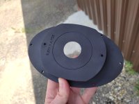
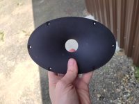
Measurement equipment, methodics, environment:
Software: ARTA
Soundcard: Creative X-Fi USB HD
Pre-Amp: IMG MPA-102
Microphone: Isemcon EMX-7150 (Class 1 FR; calibrated; Max. SPL 135 dB @ 1% THD)
SPL Calibrator: Isemcon SC-1 (Class 2, temperature & supply-voltage compensated; Accuracy +/- 0,5 dB)
Amplifier: Lab Gruppen FP10000Q
Voltmeter w/ 1,5% accuracy
Measurements were performed in a quiet, wind-free free field environment. Measurement distance was 1m. Measurements performed on axis. Setup was vertical - speaker on stand pointing upwards at 1m height of the membrane from floor, microphone on stand pointing downwards at 2m height of its diaphragm from floor.
Calibration is tested / verified before and after each measurement series.
Measurements are repeated at least once, and the result only accepted as valid / reproducable if results from two or more measurements match perfectly (within tenths of a dB).
For the sensitivity measurement, amplifier voltage (Vrms) was determined with a sine signal.
Further independent verification of my measurement accuracies: ARTA Ringversuch #3
Note that a 4pi measurement will yield a different response than one done in a box, or in infinite baffle. The driver in free air will be more affected by this, as towards lower frequencies the waves will bend backwards around its front and there will be reflection / diffraction; less so the driver in waveguide, since the waveguide, as the name suggests, itself guides the sonic output of the driver, and there will be less diffraction etc.
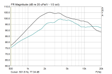
Frequency response / sensitivity; 2,45Vrms = 1 watt @ 6 ohms; floor reflections gated, 1/3oct smoothing; green curve driver in free air, black in waveguide:
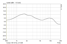
Waveguide gain - FR / sensitivity in free air subtracted from that in waveguide:
Frequency response & harmonic distortion; 2,45Vrms = 1 watt @ 6 ohms; left graph driver in free air, right in waveguide:
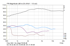
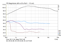
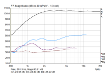
Frequency response & harmonic distortion in waveguide, filtered to as close to a flat response as reasonably possible from 2 kHz upwards, plus high pass BW18 @ 1 kHz; from left to right 90, 95, 100, 105 dB SPL (note: preset / pre-amp gain needed to be switched for the 100 and 105 dB measurements, hence the higher 3rd and 4ths that actually mostly represent the noisefloor of the signal chain):
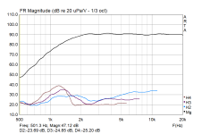
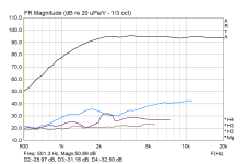

Multitone distortion (IMD & HD) in WG, filtered to as close to a flat response as reasonably possible from 2 kHz upwards, plus high pass BW18 @ 1 kHz; 6 tones / oct; EIA-426B output filter; left graph 90, right graph 100 dB SPL RMS:
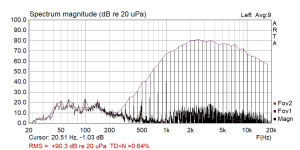
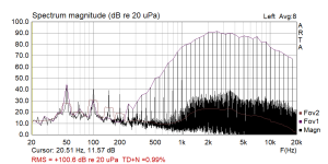
Comments: Respectable waveguide gain even down to 1 kHz. Typical horn / waveguide harmonic distortion behavior - increased K2, reduced higher harmonics. Generally superb low distortion even at higher SPLs from 2 kHz upwards. Subharmonics present in the 100 dB RMS multitone distortion measurement.
I hope you enjoyed and found the evaluation useful.
Regards
Stoneeh


Measurement equipment, methodics, environment:
Software: ARTA
Soundcard: Creative X-Fi USB HD
Pre-Amp: IMG MPA-102
Microphone: Isemcon EMX-7150 (Class 1 FR; calibrated; Max. SPL 135 dB @ 1% THD)
SPL Calibrator: Isemcon SC-1 (Class 2, temperature & supply-voltage compensated; Accuracy +/- 0,5 dB)
Amplifier: Lab Gruppen FP10000Q
Voltmeter w/ 1,5% accuracy
Measurements were performed in a quiet, wind-free free field environment. Measurement distance was 1m. Measurements performed on axis. Setup was vertical - speaker on stand pointing upwards at 1m height of the membrane from floor, microphone on stand pointing downwards at 2m height of its diaphragm from floor.
Calibration is tested / verified before and after each measurement series.
Measurements are repeated at least once, and the result only accepted as valid / reproducable if results from two or more measurements match perfectly (within tenths of a dB).
For the sensitivity measurement, amplifier voltage (Vrms) was determined with a sine signal.
Further independent verification of my measurement accuracies: ARTA Ringversuch #3
Note that a 4pi measurement will yield a different response than one done in a box, or in infinite baffle. The driver in free air will be more affected by this, as towards lower frequencies the waves will bend backwards around its front and there will be reflection / diffraction; less so the driver in waveguide, since the waveguide, as the name suggests, itself guides the sonic output of the driver, and there will be less diffraction etc.
Frequency response / sensitivity; 2,45Vrms = 1 watt @ 6 ohms; floor reflections gated, 1/3oct smoothing; green curve driver in free air, black in waveguide:

Waveguide gain - FR / sensitivity in free air subtracted from that in waveguide:

Frequency response & harmonic distortion; 2,45Vrms = 1 watt @ 6 ohms; left graph driver in free air, right in waveguide:


Frequency response & harmonic distortion in waveguide, filtered to as close to a flat response as reasonably possible from 2 kHz upwards, plus high pass BW18 @ 1 kHz; from left to right 90, 95, 100, 105 dB SPL (note: preset / pre-amp gain needed to be switched for the 100 and 105 dB measurements, hence the higher 3rd and 4ths that actually mostly represent the noisefloor of the signal chain):


Multitone distortion (IMD & HD) in WG, filtered to as close to a flat response as reasonably possible from 2 kHz upwards, plus high pass BW18 @ 1 kHz; 6 tones / oct; EIA-426B output filter; left graph 90, right graph 100 dB SPL RMS:


Comments: Respectable waveguide gain even down to 1 kHz. Typical horn / waveguide harmonic distortion behavior - increased K2, reduced higher harmonics. Generally superb low distortion even at higher SPLs from 2 kHz upwards. Subharmonics present in the 100 dB RMS multitone distortion measurement.
I hope you enjoyed and found the evaluation useful.
Regards
Stoneeh
Thanks for your trials and work!
To understand the measurements - what baffle did you use? Or completely without baffle?
The sensitivity of the tweeter seem to high? @2,45V in 1m it should not have 99dBSpl at 3,7kHz? What's happening there?
Do you also have the linearised frequency response of the tweeter without waveguide at specific levels in comparison? That would be really interesting!
I've tested the 34b in the 8'' circular waveguide and it measured higher then thatThanks for your trials and work!
To understand the measurements - what baffle did you use? Or completely without baffle?
The sensitivity of the tweeter seem to high? @2,45V in 1m it should not have 99dBSpl at 3,7kHz? What's happening there?
Do you also have the linearised frequency response of the tweeter without waveguide at specific levels in comparison? That would be really interesting!
103db at 2.83 ?
@augerpro This is an awesome project! For the CC, are you using the SB12 or SB13? If not decided yet, I believe the SB12 does not have shorting rings and measured worse in midrange distortion. I'm trying to recall whose measurements showed that but am drawing a blank, hopefully someone else recalls? In that case, SB13 may be preferable, though of course other considerations could be at play.
Also, if you ever need help with FDM printing prototypes, I'd be happy to lend a hand.
Also, if you ever need help with FDM printing prototypes, I'd be happy to lend a hand.
Okay, mayyyybe the instruction sheet didn't actually say AMYOYO. Everything else was there, though.That's a little overdramatic! Mine is from MLCS I think. And of course you slow it down to 6-8k rpm. Cuts just fine. Just take 4+ passes and be steady and slow.
In other news, have you looked at thumbnail profiles such as the Yonico 13143? It looks as if the radius starts at larger than a 1.5 inch roundover, then it gradually tightens to something like 3/4 inch or so, but by that time you don't care since the wavefront has detached from the front panel.
Comments: Respectable waveguide gain even down to 1 kHz. Typical horn / waveguide harmonic distortion behavior - increased K2, reduced higher harmonics. Generally superb low distortion even at higher SPLs from 2 kHz upwards. Subharmonics present in the 100 dB RMS multitone distortion measurement.
That makes sense since K2 for the range of 2 - 4 kHz could be focused by the waveguide as well instead of dispersing broadly, whereas a standalone tweeter would beam K3 and higher more than a waveguide would at test frequencies greater than 2 kHz. A test with the tweeter on a representative baffle as opposed to free-air might be interesting.
SB13? From their entry-level line? No I haven't. I doubt the motor is worse in the midrange line, but yes I think the 12cm does not have shorting rings. They probably have similar motors, so I'll take the white cone to match the rest of the drivers. And it has extended response on and off axis so it will be easy to work with.@augerpro This is an awesome project! For the CC, are you using the SB12 or SB13? If not decided yet, I believe the SB12 does not have shorting rings and measured worse in midrange distortion. I'm trying to recall whose measurements showed that but am drawing a blank, hopefully someone else recalls? In that case, SB13 may be preferable, though of course other considerations could be at play.
- Home
- Loudspeakers
- Multi-Way
- Open source Waveguides for CNC & 3D printing!