I can design you mic holder to print tonight. I'll need the barrel diameter and specs of the threads at the end of the boom. You really want the tip of the mic to just be a little point out in space with no reflections nearby. Here is mine, the mic slides into it and there is a slot on the bottom for the cable to exit:

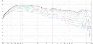
Ergo, thanks for Bliesma and WG measurement, it shows that it really has a potential. I definitely recommend to try roundovers at least R20, I have experiences with WGs of similar sizes in baffles of normal sizes, and WG responses were similar. Larger roundover always helped. I use R30. WG outter diameter is 170mm, depth 30mm.
Check the result here: SatoriWG7 :: Pkaudio
It is still not perfect, as WG profile was not machined pricely a the small diffraction at ~6kHz is probably from the midwoofer frame running into WG, next itteration will be better.
Earlier prototype with correct WG prototype was better in that regard. The baffle was just chamfered 15mm 45deg, which was not perfect in other regards (broad dip at 3-4kHz) - this made me to try R30 roundovers.
Attachments
Very cool to see and follow how this thread has evolved!
Amazing! 😀 🙂
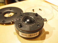
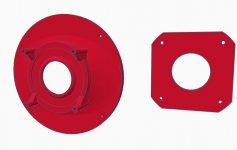
I already have the SB26ADC. When screwing of the 4 screws on the faceplate -
The dome and the faceplate are like one unit. How do I seperate the dome and the faceplate from each other?
Amazing! 😀 🙂
You can put off the faceplate of the SB26ADC and mount the dome directly to a WG.
I already have the SB26ADC. When screwing of the 4 screws on the faceplate -
The dome and the faceplate are like one unit. How do I seperate the dome and the faceplate from each other?
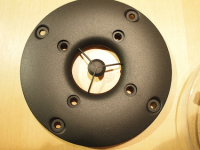
I have modified the 6" waveguide made originally by augerpro to fit ScanSpeak R2604 (also fits all other models with same faceplate, for example D2604). There is a round mounting plate that is easy to route for, diameter is 142mm, mounting depth is 6,4mm. The mounting holes are standard M4, diameter of holes is 130mm. You can use normal machine bolts to attach tweeter to waveguide with the backplate.
Dropbox - SSR2604wg.zip
Measurements coming soon when I can figure what's wrong with my measurement microphone. It shows a rapid drop-off starting from 8k, even from speakers I know can easily go past 20k...
Dropbox - SSR2604wg.zip
Measurements coming soon when I can figure what's wrong with my measurement microphone. It shows a rapid drop-off starting from 8k, even from speakers I know can easily go past 20k...
Attachments
Last edited:
In addition two THD measurements
Mic to baffle distance for THD: 315mm
I tried to keep plots comparable to the hificompass.com test
*****
All in all, not a bad result for a first attempt to find a profile for this huge dome tweeter. I will try to print a phase shield out of interest too. There is a small dimple at 7.6k that could maybe be improved a bit, but not sure yet if it is that or might it be also the baffle edges as I'm using a realistic baffle not a huge IEC type baffle here.
Congratulations! You've made a fearsome tweeter terrifying. 😀
Just for grins & giggles, have you tried a series resistor of about 8 to 12 ohms or so? Hawksford and others claim drivers show lower distortion with current drive, and a fat resistor might emulate current drive well enough to show decent results. You'd want to update the drive voltage and capacitor value, of course. The comparison won't be exactly apples-to-apples since the tweeter impedance variation would increase gain at the extrema, but setting the driver voltage to the same values in the middle of the range, say around 5 kHz, should be sufficient.
http://mariobon.com/Articoli_storici_AES/PC_Distortion_Reduction_with_iDrive.pdf
Distortion examples | Current-Drive - The Natural Way of Loudspeaker Operation
Last edited:
Thanks for the advice and the pictures! I will try that
Does the same account for the SB26STAC - The normal dome with alu frontplate.
Does the same account for the SB26STAC - The normal dome with alu frontplate.
augerpro: Do you have stl file for the 8" waveguide without phase-shield?
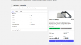
Im all new in regards to 3D printing. I found the following web-based-shop that can print in all kinds of materials.
ABS is cheapest, but nut sure if the quality is high enough.
And do you think this version is in its final stage?
Im all new in regards to 3D printing. I found the following web-based-shop that can print in all kinds of materials.
ABS is cheapest, but nut sure if the quality is high enough.
And do you think this version is in its final stage?
Attachments
Noticed the fabric SB26 has a small felt ring on top of the pole piece, while the metal versions do not:

Let's see if this new phone can capture these waveguides better:
On my SB26 Alu dome, there is a felt ring on top of the pole piece !
This is weird isnt it?
Similar on my SB26ADC as well, all 4 pieces I own.On my SB26 Alu dome, there is a felt ring on top of the pole piece !
This is weird isnt it?
Ergo, thanks for Bliesma and WG measurement, it shows that it really has a potential. I definitely recommend to try roundovers at least R20, I have experiences with WGs of similar sizes in baffles of normal sizes, and WG responses were similar. Larger roundover always helped. I use R30. WG outter diameter is 170mm, depth 30mm.
Check the result here: SatoriWG7 :: Pkaudio
It is still not perfect, as WG profile was not machined pricely a the small diffraction at ~6kHz is probably from the midwoofer frame running into WG, next itteration will be better.
Earlier prototype with correct WG prototype was better in that regard. The baffle was just chamfered 15mm 45deg, which was not perfect in other regards (broad dip at 3-4kHz) - this made me to try R30 roundovers.
Hi Pida,
On the border to off topic, but how do you make R30 roundovers?
Rockytheman: either with roundover bit or directly on cnc. I do not do it myself, I have it done by carpenter or cnc shop.
Hi Pida,
On the border to off topic, but how do you make R30 roundovers?
Question answered a while ago:
roundover bit - inch and a quarter radius
Lee Valley's site says they still ship internationally.
Thanks! Those bits are expensive though And not sure it fits my trusty Bosch router.
Augerpro: Wonder if you soon have more presents for us. Especially wish for measurements and stl files of waveguide for the SB26ADC without phase shield.
Augerpro: Wonder if you soon have more presents for us. Especially wish for measurements and stl files of waveguide for the SB26ADC without phase shield.
Thanks! Those bits are expensive though And not sure it fits my trusty Bosch router.
My Bosch came with two collets, 6.25 mm and 12.5 mm (1/4" and 1/2"). The larger roundover bits fit in the big chuck no problem, and even this terrifying thing does:
1.5 inch (38mm) roundover bit
As you point out, though, they aren't cheap -- but you may discover more projects crowding their way onto the drawing board than you'd anticipated 😀
Last edited:
Thanks! Those bits are expensive though And not sure it fits my trusty Bosch router.
Augerpro: Wonder if you soon have more presents for us. Especially wish for measurements and stl files of waveguide for the SB26ADC without phase shield.
Waiting on a batch from the printer. You can print the files I've uploaded and cut off the phase shield, or do you need it printed without ps?
DSP_Geek: Thanks! Yeah for a long time I have dreamed of beeing able to make big radius roundovers. Seems to be the best way to take care of diffraction. Thing is, if I buy it from a non EU-country, I have to pay duty fees AND around 25 USD in fee alone for handling it. On top of this we have the fee for sending it.
Augerpro. Back on post #293 i can only see the 4" inch version for the alu dome. The other named SB26 are for the soft-dome right? In post #219 you posted som nice ones for the SB Aludome (5" and 8" versions). But no stl files that I can see.
I dont mind the PS shield, but my thinking is that maybe the print will not go through or even fail. Is it only in the top end ie. aboce 10-15 Khz the response will change? (if I for instance cut off the PS).
Looking very much forward to see the new iterations!
@augerpro: First, thanks a lot for sharing all your very interesting work.
Some time ago you posted the '6x1 B v2.stl' file for a 6 inch waveguide. I would like to test this one together with the aluminum tweeter SB26ADC for using in a standard 2-way monitor plus subwoofer setup.
You never posted measurements of a 6" waveguide. So is the performance comparable to the measurements of the 8 and 5 inch versions?
Is this file still up to date? Including all you latest experiences to optimize the waveguide performance?
Last edited:
- Home
- Loudspeakers
- Multi-Way
- Open source Waveguides for CNC & 3D printing!