I cross it at 2kHz 24dB LR with a 5" WG.... no problems really. 1,3kHz is really low for a 5" IMOCrossover point I have in mind is 1,3k hz with a 24db slope. The MW13TX mid has a wide dispersion until at least 1,3k to 1,5k hz.
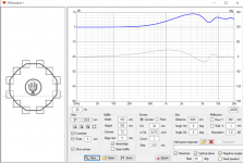
The 0 and 15 degrees are very close to each other, the sound within a normal listening window will be very even. Without knowing the baffle dimensions it's hard to speculate but the chamfers should help with the majority of diffraction The T34A is going to be wide and interact with anything that is not smooth. The inverted bowl shape of the small driver could have an effect but less so on the horizontal. The filters will have an effect across all angles, the distance to the baffle is also quite low. Too many variables that can interact to give any more solid advice.These are my initial measurements of the Bliesma T34A tweeter with @fluid 's shallow waveguide in my new 3-way.
Measurements are made with the driver and waveguide in the cabinet. Measured at a distance of 60cm. A few DSP filters were applied to get a reasonably flat response.
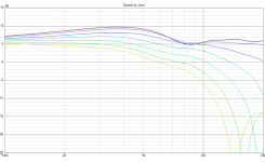
I'm not really sure what to conclude from the measurements. The waveguide seems to do something up to 5k hz. But after that it narrows again. At 20k hz there is only 9 db difference between on-axis and 60 degrees. That seems similar to HifiCompass' measurements of the T34A driver without waveguide.
And how much of it could be caused by diffraction?
That looks very nice 🙂This is how the baffle of the (unfinished) cabinet looks like:
With such a wide radiating driver as the T34A it is not advisable to try and do much more as it starts to have unintended negative consequences from the large dome size. If you saw a measurement without it you might be surprised what it actually does.joep1
That waveguide seems very shallow, almost like a flat tweeter faceplate and the diameter is small too, so it's not surprisung it doesn't do much.
It does the narrowing around 5-6kHz or that's caused by the baffle of joep1's speaker? I don't think that's caused by the crossover (1,3kHz, 24dB/oct).With such a wide radiating driver as the T34A it is not advisable to try and do much more as it starts to have unintended negative consequences from the large dome size. If you saw a measurement without it you might be surprised what it actually does.
There is nothing in the driver or waveguide to cause a localised cancellation increasing as you go off axis. It is hard to speculate on the cause of something with a lot of unknown variables.It does the narrowing around 5-6kHz or that's caused by the baffle of joep1's speaker? I don't think that's caused by the crossover (1,3kHz, 24dB/oct).
Thanks! Do you have measurement results of the Bliesma dome without and with the waveguide under the same conditions?There is nothing in the driver or waveguide to cause a localised cancellation increasing as you go off axis. It is hard to speculate on the cause of something with a lot of unknown variables.
Last edited:
The irregularity around 5-6kHz might be caused by the chamfering edge of my cabinet. That edge is at a distance of approx 6cm / 5,7kHz wavelength from the dome. I did apply a filter in DSP to reduce the on-axis hump there. So in the measurements it seems that the waveguide does something strange. But that probably is not the case at all.There is nothing in the driver or waveguide to cause a localised cancellation increasing as you go off axis.
The crossover cannot be the cause of the irregularity because it has been disabled for the measurements.
I have no measurements of the tweeter in the cabinet without the waveguide yet. But I certainly expect the waveguide to be a significant improvement!
That narrowing of the directivity would bring a pleasant drop in the sound power right in the sibilance reigon. Still very wide dispersion speaker. Careful crossing to the mid will make one heck of a BMR competitor.These are my initial measurements of the Bliesma T34A tweeter with @fluid 's shallow waveguide in my new 3-way.
View attachment 1119488
Measurements are made with the driver and waveguide in the cabinet. Measured at a distance of 60cm. A few DSP filters were applied to get a reasonably flat response.
I'm not really sure what to conclude from the measurements. The waveguide seems to do something up to 5k hz. But after that it narrows again. At 20k hz there is only 9 db difference between on-axis and 60 degrees. That seems similar to HifiCompass' measurements of the T34A driver without waveguide.
And how much of it could be caused by diffraction?
This is how the baffle of the (unfinished) cabinet looks like:
View attachment 1119490
No measurements, but simulations of a bare dome and with the waveguide (both in an infinite baffle to remove any baffle effects)Thanks! Do you have measurement results of the Bliesma dome without and with the waveguide under the same conditions?
Do you have a measurement without the filter?I did apply a filter in DSP to reduce the on-axis hump there. So in the measurements it seems that the waveguide does something strange. But that probably is not the case at all.
Measuring the driver without the waveguide in the baffle would also be helpful. Is it just a baffle or a complete cabinet?
1m is a reasonable distance for an indoor measurement, further is better unless it is to be listened to up close.
.
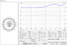
This is a measurement without filters, from 1m distance:Do you have a measurement without the filter?
It is a complete cabinet, with all drivers mounted, bracing and damping applied already. The baffle is 26.4cm wide, chamfers are 30 degrees and have a minimal distance of 8mm from the waveguide. Distance from top of the waveguide to top of the baffle is 3.2cm.Is it just a baffle or a complete cabinet?
That makes things much clearer, the filter you applied was the cause of the off axis response issue.
The real culprit is some diffraction around 7 to 10K causing the on axis and 15 degree traces to be at virtually the same level as the 30 degree trace. This is not something that can be equalized for very easily, boosting the on axis will cause a peak off axis in the same way as cutting on axis before pronounced an off axis dip.
The general trend follows the green line and this is the slope I would equalize to flatten the design axis.
The small blue arrow shows there is a slight off axis depression that moves in frequency, this is also nothing that can be equalized successfully.
Any filter used to flatten the design axis response that makes the off axis responses worse should be avoided, particularly if the design axis is 0 degrees as this will suffer the greatest level of diffraction effects than any other.
As an example the kind of things that will take to EQ are the hump at 2.7K and the peak at 10.5K.
Thanks @fluid, that is very interesting and really helpful !!!
I will redo the filtering and re-measure the result.
I still wonder if chamfering the sharp top edge of the baffle also by a 30 degree angle might reduce some of the issues. The distance from the dome is about 8.5cm, which might cause the on axis peak around 6.2khz and dips around 4.2khz and 8.5khz. Any thoughts on that?
Chamfering the top does not always help, it will create a difference but it isn't always a positive one. Counter intuitively super wide drivers like the T34A don't always benefit from angled chamfers in the same way more directive drivers do. A larger baffle with reasonable edge rounding diameter or a wide baffle with really large gentle rounding can work better sometimes if the baffle shape is chosen carefully.I still wonder if chamfering the sharp top edge of the baffle also by a 30 degree angle might reduce some of the issues. The distance from the dome is about 8.5cm, which might cause the on axis peak around 6.2khz and dips around 4.2khz and 8.5khz. Any thoughts on that?
You might want to try a measurement with the mid driver hole blanked off flush so you can see if the mid driver cone and structure are contributing.
Consider putting your measurements into Vituixcad, that way you can see what effect the EQ has on all angles simultaneously without needing to remeasure.
Hi,
If its diffraction related we can try estimate it with diffraction tool. Trying to replicate the "bundling" around 7-10kHz, worst case scenario round baffle with ideal flat 34mm source in the middle, it looks like about 75mm diameter "edge" or feature that makes diffraction would make similar bundling.
If features in the measurement are due to diffraction it seems some feature in the build about ~75mm in diameter (or ~40mm from the center of the tweeter) that makes features in the measured response, perhaps the small gap between waveguide and baffle? If the waveguide bigger like 100mm in diameter then the gap would make the response charasteristics somewhat lower in frequency instead and its probably something else.
100mm round edge makes feature bit lower in frequency, on-axis dip around 6-7kHz.

Speculating that edge making diffraction needs to be closer than this, trying 75mm seems to lineup with measured response, on-axis dip ~8-9kHz:


If its diffraction related we can try estimate it with diffraction tool. Trying to replicate the "bundling" around 7-10kHz, worst case scenario round baffle with ideal flat 34mm source in the middle, it looks like about 75mm diameter "edge" or feature that makes diffraction would make similar bundling.
If features in the measurement are due to diffraction it seems some feature in the build about ~75mm in diameter (or ~40mm from the center of the tweeter) that makes features in the measured response, perhaps the small gap between waveguide and baffle? If the waveguide bigger like 100mm in diameter then the gap would make the response charasteristics somewhat lower in frequency instead and its probably something else.
100mm round edge makes feature bit lower in frequency, on-axis dip around 6-7kHz.

Speculating that edge making diffraction needs to be closer than this, trying 75mm seems to lineup with measured response, on-axis dip ~8-9kHz:


Last edited:
Been scanning the thread but haven't seen much on 3/4" dome tweeters and WG paired with them. Perhaps I am chasing the wrong thing but the best imaging I've personally heard was on the behringer 2030p. The passive model was discontinued a long time ago, only active remains and the amps have some annoying issues that made me return them. I've had KH80 and 8030c, Focal Alpha, HS8, and DIY Amiga and none of them gave me what the Behringers did. I mixed a lot of music on those, the woofer has its issues but man, that tweeter I very much miss. I'd love to DIY my own solution without the drawback of unreliable amplifiers (they also send out a massive pop when powered on).
I've got a WG300 and adapter for the various SS and peerless tweeters, but not sure if I want to really invest in it.
I've got a WG300 and adapter for the various SS and peerless tweeters, but not sure if I want to really invest in it.
My website has waveguides for a 3/4" Scanspeak Revelator, Vifa ring radiator, an SB Acoustics SB21SBC
Hi Brandon!
Hope you are doing well! Do you have any developments on the DIY speaker family using SB Acoustics SB17CAC and SB26CDC version?
Cheers and good luck
Hope you are doing well! Do you have any developments on the DIY speaker family using SB Acoustics SB17CAC and SB26CDC version?
Cheers and good luck
I was listening to the prototype the last two days. Cutting wood today to try some different ideas. I'm slow, but the project is progressing!
Excellent news! If you can, please share some pictures / feedback to reduce the anxiety !I was listening to the prototype the last two days. Cutting wood today to try some different ideas. I'm slow, but the project is progressing!
Cheers
- Home
- Loudspeakers
- Multi-Way
- Open source Waveguides for CNC & 3D printing!