That's true that MOSFET drivers can be made to operate in a linear fashion, like in the UcD180.
Intent is to make working this CFA schematic without oscillations, preferably with balanced input
Thank you for the asc, checked it in LTspice...
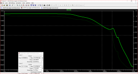
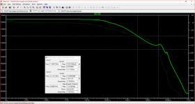
AC-analysis shows the instability in the region of 10MHz.
For my opinion, transit frequency is way too high considering the slow sziklay output stage - not the first choice for fast switching bipolars.
Keep in mind that ac-analysis is restricted to linear range of transfer function (small signal), that is switching delays (large signal) are not simulated.
Transit frequency of output bipolars is 30MHz. As a consequence their current gain starts to drop at 0,5~1MHz, with an initial phase shift of 45 degrees.
Imho there is no point in building an ultrafast cascode driver with a medium speed power stage: Closing the overall feedback loop requires an appropriate dominant pole compensation with reduced transit frequency.
You may have a look at a dominant pole compensation.
This solution bypasses the feedback loop for high frequency signals delayed by the output stage.
Which is a great benefit concerning stability.
This solution bypasses the feedback loop for high frequency signals delayed by the output stage.
Which is a great benefit concerning stability.
Attachments
Last edited:
Thank you for the asc, checked it in LTspice...
AC-analysis shows the instability in the region of 10MHz.
For my opinion, transit frequency is way too high considering the slow sziklay output stage - not the first choice for fast switching bipolars.
Keep in mind that ac-analysis is restricted to linear range of transfer function (small signal), that is switching delays (large signal) are not simulated.
Transit frequency of output bipolars is 30MHz. As a consequence their current gain starts to drop at 0,5~1MHz, with an initial phase shift of 45 degrees.
Imho there is no point in building an ultrafast cascode driver with a medium speed power stage: Closing the overall feedback loop requires an appropriate dominant pole compensation with reduced transit frequency.
I heard CFP output stage is best in linearity and bandwidth. Is there any better output stage invented? Emitter follower is inferior to CFP.
You may have a look at a dominant pole compensation.
This solution bypasses the feedback loop for high frequency signals delayed by the output stage.
Which is a great benefit concerning stability.
Thanks.
Is it possible to realize it in practice 11p 33p 99p? However there is still some instability in 10MHz region.
Can we use here three alternative methods of compensation, which are supposed to allow greater open loop bandwidth while still maintaining amplifier closed loop stability: lead compensation, lead–lag compensation and feed-forward compensation?
Last edited:
I have found two ways to stop oscillation:
1/ Increase VAS capacitor to 100pf.
2/ Put 10R resistors between driver and output stage on bi-polar amps.
1/ Increase VAS capacitor to 100pf.
2/ Put 10R resistors between driver and output stage on bi-polar amps.
Better Stability
I did a simulation I thought solved the stability issues in this circuit a couple of months ago. I was undecided about posting it then and forgot about it since the interest went quiet.
I have done a Bode simulation which is now attached.
I am hesitant to post the .asc file as the emitter resistor values I see as problematic.
Attachments
I have found a problem with some designs where the amp is designed to run at as high frequency as possible. Then the damping is made so it is just below oscillation.
Then with spreads in transistor specs the next build can sometimes oscillate.
Then with spreads in transistor specs the next build can sometimes oscillate.
Yeah Nah Response
That is a very good point.
I used 200 pf in my original version of this simulation (for square wave into 8R//2uF Quad 63 load) but cut this down to 100 pf - the same value you suggested.
These - C36 and C38 are connected respectively between collector Q18 and base Q14 and collector Q17 and base Q16.
For some subscribers high frequency performance is the holy grail and they would be unimpressed with the result attached.
Attachments
Last edited:
I explained the problem with this circuit 3 months go. This is the wrong way to make a balanced amplifier, even though it might appear to work on the surface.
Here we are 3 months later and things have come full circle. You cannot get this circuit to work right because it is a flawed design.
Okay, forget all this. The circuit as posted in the first post won't work.
Putting a second input pair on a CFA will not work as a negative input, although it would be nice if it did.
...
No one expected the problem to be this bad, which is why after all this time and the opinions of many experts no one realized the problem.
I hate to bring the bad news, but look at it this way. You no longer have to spend any more of your or anyone else's energy on this circuit. Instead you might be able to get started on the right path and finally do what you had originally intended to do.
Here we are 3 months later and things have come full circle. You cannot get this circuit to work right because it is a flawed design.
There are simulations with the so-called "balance structure" deleted - I not looking at anything else.
I'm talking about the simulation AndriyOL posted. This is his thread, so I can only assume it is about his circuit and the other things are just detours along the path.
Thank you for the asc, checked it in LTspice...
AC-analysis shows the instability in the region of 10MHz.
For my opinion, transit frequency is way too high considering the slow sziklay output stage - not the first choice for fast switching bipolars.
Imho there is no point in building an ultrafast cascode driver with a medium speed power stage: Closing the overall feedback loop requires an appropriate dominant pole compensation with reduced transit frequency.
Dear Voltwide:
Can you comment about the effect that cascodying also the output stage would have on stability???
(I am just beginning familiarity with LTspice... 🙁 )
Thanks,
M.
I read this post before, the design is original of Lazy Cat, not Andriy design, why don't you Andriy build a amplifier which has already designed and working???
If you want true balanced you should build a bridge amplifier. So many people try to help but you don't accept it is not working... sorry but I must borrow a comment from another guy...
good luck with this Don Quixote journey!
If you want true balanced you should build a bridge amplifier. So many people try to help but you don't accept it is not working... sorry but I must borrow a comment from another guy...
This is a variant of the old "I don't understand what I am doing , but everything people are telling me is wrong"....
good luck with this Don Quixote journey!
Last edited:
Dear Voltwide:
Can you comment about the effect that cascodying also the output stage would have on stability???
(I am just beginning familiarity with LTspice... 🙁 )
Thanks,
M.
To make the power stage faster, the first I would do replace the sziklay by a regular 2 or 3 stage darlington stage. This topology enables fast base turn off of output transistors. You may go further with complementary base driver circuits.
Decades ago I played this game with 2N3055H. The results were not so impressive. Luckily lat-FETs entered the scene at that time and since then I lost interest in optimizing bipolar power amps.
To answer your question - I never digged in cascode output stages - just because I like to keep things as simple as possible.
LTspice is a nice tool, but you should always keep in mind its limitations. AC-analysis does not cover large signal / switching effects. So I recommend to evaluate stability with transient analysis at various signal levels as well as ac-analysis.
To make the power stage faster, the first I would do replace the sziklay by a regular 2 or 3 stage darlington stage.
Do you mean like this?
Attachments
I have found two ways to stop oscillation:
1/ Increase VAS capacitor to 100pf.
2/ Put 10R resistors between driver and output stage on bi-polar amps.
Could you post a sim?
Thanks very much for your opinion and advices.To make the power stage faster, the first I would do replace the sziklay by a regular 2 or 3 stage darlington stage. <snip>
The reason I ask, and though I recognize the benefit of KISS strategy, is because I am more inclined to try non-popular ways of doing things, even if that makes the fumes appear...
I have an all BJT-VSSA, with cascaded/cascoded outputs running for months on the patio system, so far stable (39pF CDom; no zobel) and better sounding IMHO than the regular one. Maybe it was pure luck...
That strategy would take care to some extent of the base charges, given the proper configuration...
I am oriented to Lin topology nowadays...lots of study still 😱
Next move for me is cascoded-CFP output.
A question about your last post: wouldn't the two bases of Darlington make for bigger charges?
Best wishes,
M.
PS: cascoded-Mosfet outputs also sound good. 😉
Last edited:
A question about your last post: wouldn't the two bases of Darlington make for bigger charges?. 😉
The dominant base charge resides in the output devices solely, driver charge is at least one order of magnitude lower.
- Home
- Amplifiers
- Solid State
- One of the Top Solid-State CFA amp design