JPV said:The initial question was: the temco of the diode and of the Vbe of the transistor are not the same for the 3XXX series at normal bias current in the diode ( whatever this means)
It seems that looking at the datasheet of the 4XXX, the tempcos are the same around 10mA in the diode.
JPV
It looks like the 3xxx series is designed for Leach type Vbe multipliers with ~1ma current, and the 4xxx series is designed for series connection in a VAS stage with ~10ma current.
I use Sanken 2SA1215Y and 2SC2921Y with a Leach Vbe multiplier VAS circuit that uses separate diodes epoxied on the back of the Sanken packages. The Leach Vbe multiplier puts ~1ma through these series diodes. I use 2NPN+2PNP epoxy glued diodes for 4NPN + 4 PNP transistors on each half of a SuperSymm topology.
(a) Because of the large thermal mass of the heatsink and the different thermal paths of the ThermalTrak diode die vs. transistor die, will diodes glued on the back of a Sanken package have superior thermal tracking to ThermalTraks?
(b) SPECIFICALLY: Does the 3xxx ThermalTrak offer superior tracking to rear-package epoxied diodes in a Leach circuit?
Thanks for any help on these basic questions.
SEE Post #185
"An experiment that can validate how well N-diodes in the Leach Vbe multiplier can compensate for K-output transistors using the ThermalTrak Tc factors would be very useful."
Attachments

JPV said:
Ok the more date the better. But what we realy need is the Vbe drift around 100mA. The tempco coefficient is changing by 0.2mV/°C per decade of current. Therefore, if we know it at 100 mA the drift mill be nearly the same at other realistic currents.
The Vbe change at constant temperature should be 60mV per decade of current.
JPV
As you say it is "nearly the same", with the data I'm suggesting we don’t have to guess, but will know.
Stinius
LineSource said:
It looks like the 3xxx series is designed for Leach type Vbe multipliers with ~1ma current, and the 4xxx series is designed for series connection in a VAS stage with ~10ma current.
I use Sanken 2SA1215Y and 2SC2921Y with a Leach Vbe multiplier VAS circuit that uses separate diodes epoxied on the back of the Sanken packages. The Leach Vbe mltpilier puts ~1ma through these series diodes. I use 2NPN+2PNP epoxy glued diodes for 4NPN + 4 PNP transistors on each half of a SuperSymm topology.
(a) Because of the large thermal mass of the heatsink and the different thermal paths of the ThermalTrak diode die vs. transistor die, will diodes glued on the back of a Sanken package have superior thermal tracking to ThermalTraks?
(b) SPECIFICALLY: Does the 3xxx ThermalTrak offer superior tracking to rear-package epoxied diodes in a Leach circuit?
Thanks for any help on these basic questions.
SEE Post #185
"An experiment that can validate how well N-diodes in the Leach Vbe multiplier can compensate for K-output transistors using the ThermalTrak Tc factors would be very useful."
The Leach muliplier allows to use 4 diodes in the base leg to generate 6 diodes drop of the triple T Locanthi/Leach output toplogy. The number of // ouput transistors is irrelevant.
Being able to tune independently the tempco of the diodes in a Leach Vbe multiplier with the help of a spectrum analyzer will give IMHO the best crossover distortion avoidance.
JPV
stinius said:
As you say it is "nearly the same", with the data I'm suggesting we don’t have to guess, but will know.
Stinius
The idea is to know if you have the headroom for adjustments.
You will have to adjust using a spectrum analyzer anyway.
The 0.2mV/°C change in tempco is basic solid state physics.
JPV
Yes I know that, but anyway we agree that the measurement must be done with constant collector current.
Stinius
Stinius
Hi all, I read all 13 pages and since I design loudspeakers a great deal went high over my head, much like a stiff breeze.
This thread started because of a magazine circuit.
These modules can be purchased in bulk for $AU50.00 ea. That's about $US33.00.
May I suggest a little work on that design with a few mods may give many who can't afford more expensive amps a chance to build something special.
Just a thought, yes I do need some amps for a project, problem is I need 10 amplifiers, 😕 five per speaker!
pheonix358 said:Hi all, I read all 13 pages and since I design loudspeakers a great deal went high over my head, much like a stiff breeze.
This thread started because of a magazine circuit.
These modules can be purchased in bulk for $AU50.00 ea. That's about $US33.00.
May I suggest a little work on that design with a few mods may give many who can't afford more expensive amps a chance to build something special.
Just a thought, yes I do need some amps for a project, problem is I need 10 amplifiers, 😕 five per speaker!
So you have read all 13 pages in this thread and think it is about a kit from a magazine?
And you have some ideas to improve the kit?
You say “a great deal went high over my head, much like a stiff breeze.”
I don’t think it’s a breeze, but more like a hurricane or even worse, we are talking about a really hard storm.
I really don’t mean to be sarcastic, but it seems like you don’t have the slightest idea of what we are talking about in this thread.
Stinius
Read post 19 and try not to be such a dick. You enjoy being sarcastic and revel in putting others down. My post was honest. I have 20+ years as a loudspeaker designer in Australia, was Aussy distributer for Morel and Clio systems. What's your claim to fame!
pheonix358 said:... try not to be such a dick.
Careful. We use "richard" here.
🙂
DouglasSelf said:
Hi
I am confused. What is a copper preform? Is it something that goes between the die and the metal plate? If so what holds it all together?
If the diode is mounted using insulating epoxy, that doesn't affect the rough calculation I did in the steady state, providing there is no significant heat loss from the diode. But there may be- this is why I would like to know the construction details. Certainly epoxy rather than solder would increase the time-lag.
I fear that to get a real feel for this we need a proper Finite Element Analysis of the package, and to do that we would need more data about the device than we are ever likely to get.
Does anyone know of a freeware FEA package? They do exist, because I was sent one, but the instructions are in Russian...
What about the following test.
Adjust the Vbias for 100mA in the output transistors with no signal
then by switching a resistor in the Vbias circuit, increase in one step the output bias current to 1A. without signal. This will be a nice step in power and allows to measure the ouput current and the Vbe while drift is operating. This will give accurate view of tracking dynamics.
JPV
peranders said:
If you Google Mr Self you'll find stuff about copper preform. I just did
Astonishingly, I did just that. I got a lot of stuff about brazing, which given the temperatures required (450degC) doesn't sound as if it would be a good way to construct transistors.
Do you have anything constructive to offer?
An externally hosted image should be here but it was not working when we last tested it.
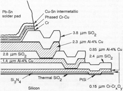
That is a copper preform (on semi -njw0281) t-trak has sameBy d.self - I am confused. What is a copper preform?
die but with integrated diode. There seems to be a very thin
layer of grey conductive epoxy under silicon, molded HIGH
impact thermoplastic on top..

Have smashed blown sanken OP devices w/internal diode
comp. ,same construction..
MJL21193 said:
Careful. We use "richard" here.
🙂
Careful again! Where I live we still use cockney rhyming slang; "richard" derives from "Richard the Third"...
http://www.aldertons.com/english_to_slang.htm
EDIT
and the slug.. It is usually copper/moly/cadnium..etc (an alloy)
and seals the semi in place.. a pix will suffice
It does have to do with brazing..BTW
That is the slug.. the preform is the barrier which is deposited between the substrate of the chip (junction)That is a copper preform
and the slug.. It is usually copper/moly/cadnium..etc (an alloy)
and seals the semi in place.. a pix will suffice
It does have to do with brazing..BTW
DouglasSelf said:
Careful again! Where I live we still use cockney rhyming slang; "richard" derives from "Richard the Third"...
http://www.aldertons.com/english_to_slang.htm
Sorry to be off topic, but I hoped I could use the avatar:
Battle of Bosworth Field, with King Richard III on the white horse.
Now it seems I have to use Hugh Jamton (Spike Milligan)
😀
Stinius
DouglasSelf said:
Careful again! Where I live we still use cockney rhyming slang; "richard" derives from "Richard the Third"...
http://www.aldertons.com/english_to_slang.htm
🙂
A dictionary of droog speak. Now I can decipher WTF young Alex is saying in A Clockwork Orange 😀
JPV said:
The results from Douglas ( higher Vbe multiplication and higher tempco required) remains unexplained.
JPV
I do hope that someone is going to replicate my experiments. So far as I can tell I am the only one who has built and measured a TTrak amplifier so far. My tests had to be done in rather a hurry and I would be glad to see some confirmation that I didn't screw up.
I will be happy to supply the complete circuit of the test amplifier to anyone who wants it.
ostripper said:EDIT
That is the slug.. the preform is the barrier which is deposited between the substrate of the chip (junction)
and the slug.. It is usually copper/moly/cadnium..etc (an alloy)
and seals the semi in place.. a pix will suffice
It does have to do with brazing..BTW
Still not clear to me. Your picture shows "silicon" as the bottom layer. Where's the preform and the slug?
Slug = metal plate??
And where does brazing come in?
- Status
- Not open for further replies.
- Home
- Amplifiers
- Solid State
- On Semi ThermalTrak