The problem with using a diode is that it forms a nice bridge for any mains noise into the rest of the equipment.
jd
No one has a better way to get around it, so were stuck with them.
the better way is to add a series resistor to each capacitor across the diodes and trim the cap + resistor values until the snubber ideally damps the spike and HF ripple created by the diode capacitance and the transformer inductance.No one has a better way to get around it, so were stuck with them.
the better way is to add a series resistor to each capacitor across the diodes and trim the cap + resistor values until the snubber ideally damps the spike and HF ripple created by the diode capacitance and the transformer inductance.
I had a quick chat about this with my buddy and he said it better off to use a buffered LM317 to achieve instrument grade power supply 🙂
Regulated version posted in the power supply thread...
Now just need to start my own thread and stop littering these 2
Now just need to start my own thread and stop littering these 2
From post 519 and 520
So, I've built and tested this configuration with an LME49811 as the VAS and predriver and 15032/33 as drivers. I can't get enough bias sensitivity to hold the bias constant regardless of temperature. In all cases the bias rises with temp - the amount of rise is affected by the R3/R2 choice.
I've tested the 10k/893 and the 3k/2142 versions and get the following results. I'm using a hand held infra-red temp measurement device.
10k/893
29.4C = 29mA
37C = 38mA
9mA/7.6degC = 1.18 mA rise / degC
3k/2142
25C = 27mA
39C = 38mA
11mA/14C = .78 mA rise / degC
The target would be 0 mA rise / degC
Is there a way to get more sensitivity from this circuit?
Ken
As mentioned above, R3 acts to enhance and control the sensitivity to the TC of the tracking diodes. The numbers below show the sensitivity to the tracking diodes as a function of R3. In all cases the spread was adjusted to produce 26 mV across the output emitter resistors. Sensitivity is defined as the change in voltage base-to-base of the output transistors divided by the change in voltage of D1 + D2. Notice that sensitivity is less than unity in a simple arrangement without R3. Also note that in some previous postings there has been some discussion about the need for the sensitivity to be substantially greater than unity. The numbers shown here provide sensitivity values up to about 1.5:1.
R3...... R2...... sensitivity
Infin... 716..... 0.92
20k..... 794... 1.01
10k..... 893... 1.10
7.5k ... 974 ... 1.16
5.0k.... 1190... 1.28
4.0k... 1430... 1.37
3.0k... 2142... 1.52
Cheers,
Bob
So, I've built and tested this configuration with an LME49811 as the VAS and predriver and 15032/33 as drivers. I can't get enough bias sensitivity to hold the bias constant regardless of temperature. In all cases the bias rises with temp - the amount of rise is affected by the R3/R2 choice.
I've tested the 10k/893 and the 3k/2142 versions and get the following results. I'm using a hand held infra-red temp measurement device.
10k/893
29.4C = 29mA
37C = 38mA
9mA/7.6degC = 1.18 mA rise / degC
3k/2142
25C = 27mA
39C = 38mA
11mA/14C = .78 mA rise / degC
The target would be 0 mA rise / degC
Is there a way to get more sensitivity from this circuit?
Ken
From post 519 and 520
So, I've built and tested this configuration with an LME49811 as the VAS and predriver and 15032/33 as drivers. I can't get enough bias sensitivity to hold the bias constant regardless of temperature. In all cases the bias rises with temp - the amount of rise is affected by the R3/R2 choice.
I've tested the 10k/893 and the 3k/2142 versions and get the following results. I'm using a hand held infra-red temp measurement device.
10k/893
29.4C = 29mA
37C = 38mA
9mA/7.6degC = 1.18 mA rise / degC
3k/2142
25C = 27mA
39C = 38mA
11mA/14C = .78 mA rise / degC
The target would be 0 mA rise / degC
Is there a way to get more sensitivity from this circuit?
Ken
Hi Ken,
Can you post a schematic of the whole arrangement that you have got?
BTW, note that the LME49811 is only rated to supply 6.5 mA to the Vbe multiplier. I don't recall how much I designed that Vbe multiplier for in the example, but I usually design for 10 mA.
Also, your quiescent bias numbers for the output stage seem awfully small. If you are using a single pair of ThermalTrak BJTs with 0.22 emitter resistors, bias should be on the order of 120 mA.
If you are using a CFP output stage, you should probably be using something else.
I'm assuming from what you've said that you are using a Locanthi Triple EF output stage where the pre-drivers are inside the LME49811.
Cheers,
Bob
Hi Bob,
I was using the small bias based upon recommendation from AudioMan54 - Mark. I can easily dial the bias up - I had it at 350mA the other day by accident...
I'll post the schematic tonight. Yes, it's the Locanthi Triple EF just as you describe.
Ken
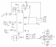

Bob,
Here's the schematic in two parts, the LME49811 and then the CAS.
Regarding bias level, could setting it at a higher level affect the thermal compensation?
Ken
Seems to me that the variable resistor is at a wrong place
in respect of an eventual failure of this component.
Hi wahab,
Absolutely!
Hi Ken,
Try to rework that so an open control will cause the bias to drop to zero. The position between the emitter and base would be normal for this.
-Chris
Absolutely!
Hi Ken,
Try to rework that so an open control will cause the bias to drop to zero. The position between the emitter and base would be normal for this.
-Chris
Is there anyone out there who knows which of these thermaltrak transistors used by McIntosh Mc2kW ?..or which these can be an equivalent Output..thanks
NJL0302DG 180W NPN
NJL0281DG 180w PNP
NJL3281D 200W PNP
NJL1302D 200W NPN
NJL4302DG 250W NPN
NJL4281DG 250W PNP
NJL21193DG 200W PNP
NJL21194DG 200W NPN
NJL0302DG 180W NPN
NJL0281DG 180w PNP
NJL3281D 200W PNP
NJL1302D 200W NPN
NJL4302DG 250W NPN
NJL4281DG 250W PNP
NJL21193DG 200W PNP
NJL21194DG 200W NPN
Is there anyone out there who knows which of these thermaltrak transistors used by McIntosh Mc2kW ?..or which these can be an equivalent Output..thanks
NJL0302DG 180W NPN
NJL0281DG 180w PNP
NJL3281D 200W PNP
NJL1302D 200W NPN
NJL4302DG 250W NPN
NJL4281DG 250W PNP
NJL21193DG 200W PNP
NJL21194DG 200W NPN
hi Ric, do you own one? you can reach me at 6282996.....we can chat....😀
Thanks Jacco, this will be my stepping stone to build the Mc2kw..I'm in the process of making the PCB..Would you mind if ask where I can find the source of this latest catalog of McIntosh Semiconductor Data? It's a good thing to have this because its difficult to interpret McIntosh house ID..
Hi Tony..I'll be calling You.
Hi Tony..I'll be calling You.
Hi Jacco, I'm back to you..Sorry, cant find either ECG or SK manual in hometown to search even equivalent numbers for Mc2KW transistors..I am still after for a few tr's for its preDriver stage. I have been struggling to start DIYing this amp and was nowhere to find its mcintosh house numbers. Other parts are no problem..can you provide once more?..if so, I'll post the numbers..
Thanks...
Thanks...
The MC2KW is current McIntosh production, i respect that.
Would be a different story if the amp model was discontinued.
Would be a different story if the amp model was discontinued.
This minute I got 5 pairs ( matched so the vendor claims ??) NJL4281D / NJL4302D at internet auction nice price but not sure what to do with it. The ultimate thermal stability
of queiscent current is still achieved by the QUAD 303 triple cascade but this has dynamic constraints. I would use the trak diodes to control the bias of a standard Vbe multiplier which is not in thermal contact with heatsink.
Further at least subjectively but not measurable with software thd spectrum analyser it has turned out that to keep all of the BJTs of an amp predriver Vas drivers at a constant temperature as these are mounted on a common heatsink the temperature of which is controlled by a thermostat circuit.
- Status
- Not open for further replies.
- Home
- Amplifiers
- Solid State
- On Semi ThermalTrak