John
I think you are doing a great job and research.
I look forward to your next posts.
Stinius
I think you are doing a great job and research.
I look forward to your next posts.
Stinius
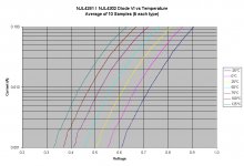
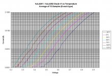
jgedde said:I wasn't able to finish all the temperature runs today. Still left to do are 100 and 125 degC for the diode, and a tempco determination of the transistors. All will have to wait until tomorrow. So far, it seems the datasheet is very close to reality. By this time tomorrow, we will know all... Then, on to verifying/tweaking the PSPICE model for the diode...
What should I run for base current for the transistor tempco tests? I'd like to keep self-heating to a minimum, but still get a tempco that's at a reasonable value.
Hmmmm. I was just thinking... What if I used another Tek 576 (I have three) to drive the transistor, and use another to look at the diode. Then I'll capture how the diode reacts to load changes in the transistor. In other words, how long it takes to stabilize to a new curve. Just speculating. I have already spent way too much time on this..... 🙂 Oh well, it's for a good cause. So far, you folks have been invaluable to me in sharing your experience and "lessons learned." I guess, even if I do this test, I'll still end up ahead time-wise given that the advice given to me over the past two years has saved me a lot of wasted time...
John
Because the objective is to minimize crossover distortion with transient variation in temperature, I believe that it is important to know the Temco of the transistor Vbe around 100mA bias current ( optimal bias for 0.22ohms in the emitter) in the 300 and 400 °K range. Variation of Tempco is minimal with 100% variation of Ibias
For the diodes, more information is needed and checking if the datasheet is correct is important.
Normally knowing two points per current is enough:
Vbe at 300 and 400 °K for different constant currents ( a few steps of 100 micro amps around one milliamp and then steps of one milliamp including a 10 mA measurement).
The different current steps can be done at one temperature and then repeated at the second temperature. These small steps will see the Vbe settling rapidely and the overall measurement should not be too long (IMHO). We then can plot the data on a graph and see if they extrapolate well to the band gap voltage.
Here is a confirmation of the -0.2mV/°C change in Tempco per decade of decrease of current.
http://www.national.com/rap/Story/vbe.html
This would also allow you to choose the right current in the diode to perform your ultimate test with two 576. With all this, we will know!!
These are only suggestions.
Thanks for your help
JPV

Bob Cordell said:
Hi Doug,
This is nice work and interesting results. I think that before looking at THD vs time, one should look at bias current vs time after startup and after a big thermal transient.
Bias the amp optimally in thermal steady state (e.g., 26 mV across each Re or whatever the right value is for those particular ThermalTraks - it will be less) and then look at the emitter-to-emitter voltage vs time to evaluate the thermal stability in idle from a cold start.
More importantly, one should look at a measure of the output stage bias current immediately after a 1/3 power signal is fed through the amplifier.
This is the sort of thing I illustrated in my MOSFET with EC amplifier paper, where I compared thermal stability of bias for MOSFETs vs BJTs.
Cheers,
Bob
Hi Bob
Sorry it's taken so long to get back to you on this one.
If I understand you correctly, measuring Vq (emitter-to-emitter voltage ) versus time is going to require a differential amplifier which is accurate to less than 1 mV, connected to some sort of recorder. A bit of specialised kit to build, whereas the AP was sitting right there.
The problem I see with this is that it is not possible to measure what's happening when the amplifier is working; only before and after a burst of power.
I certainly don't think that the under-biased-THD-vs-time method is perfect. For one thing, it relies on having the bias set too low, so the multiplication factor of the Vbe-multiplier (or equivalent) will be slightly less than for optimal bias and this might throw things off, depending on the details of the circuitry.
I have been wondering if the same measurement could be done with optimal biasing. Take a Blameless amplifier, and the distortion products at 10 kHz will be entirely due to the crossover, even if optimal. You could measure 10 kHz THD vs time, and this might give meaningful results. The problem would be that any deviation from optimal bias will increase the THD, so it will be hard to distinguish over-biasing from under-biasing, unless you sit and watch the residual and take notes. I think it might be worth a try.
The results are close to the data sheet.
Can you make the 3XXX data at a lower peak current like max 10mA to have a correct resolution at 100 micro amp
It seems that resistance starts to influence above 10mA.
JPV
Can you make the 3XXX data at a lower peak current like max 10mA to have a correct resolution at 100 micro amp
It seems that resistance starts to influence above 10mA.
JPV
A very useful thread..not just for T-trak lovers. The finer aspects
of the Vbias circuit are portable to us poor slobs with our
cheap 0281's and mj15003's ,too.
I've got it refined and found that a trimmable coefficient in
the Vbe combined with the proper tranny and placement
can provide optimal results..
Thanks, D.Self and others for a very informative thread..🙂
OS
JPV said:Although very little power is dissipated in the drivers, the transient part of this experiment is perhaps very sensitive to delta T°.
An initial delta T of 5°C between the driver junction and Vbe transistor junction generates a 20mv increase in Vq bias which will influence a lot the THD reading.
A way to test for this would be to disconnect the power stage instead of switching off the full amplifier and then when cold switch it again on. The increase in power dissipation in the class A driver is way less. This can be done without risks if using a resistive load.
It would be an interesting experiment to rule in or out the influence of the driver in the long term drift which is puzzeling.
JPV
Hi JPV
I have thought about doing tests with an amplifier at thermal equilibrium so that start-up effects are not present. (though it should be possible to find out what they are)
The problem is that if you disconnect the load then the crossover distortion disappears so, as with measuring Vq, you cannot get any data for about half the time, which is not helpful.
At the moment I'm considering the "heatsink cosy" approach. Let the amplifier reach equilibrium (and that will take about an hour) and start measuring crossover THD from under-biasing. Now put some thermal insulation on the heatsink so it goes up in temp by say 30 degC. That should give a good-sized thermal transient which will put the compensation to the test.
DouglasSelf said:
Hi JPV
I have thought about doing tests with an amplifier at thermal equilibrium so that start-up effects are not present. (though it should be possible to find out what they are)
The problem is that if you disconnect the load then the crossover distortion disappears so, as with measuring Vq, you cannot get any data for about half the time, which is not helpful.
At the moment I'm considering the "heatsink cosy" approach. Let the amplifier reach equilibrium (and that will take about an hour) and start measuring crossover THD from under-biasing. Now put some thermal insulation on the heatsink so it goes up in temp by say 30 degC. That should give a good-sized thermal transient which will put the compensation to the test.
Hi Douglas
What I was thinking is to keep the driver hot ( signal on) while the output stage is disconnected ( via optocoupled Mos gates in serie with the base of the output transistors or perhaps a relay). Then when cold, the ouput stage is switched in ( on a hot driver ) and THD measurement can proceed but with less thermal transient due to the driver.
But your idea is great. Why not use a fan cooled heatsink and then switch off the fan?
JPV
That works VERY good... I use 4 P4 heatsinks with 80mm fansBut your idea is great. Why not use a fan cooled heatsink and then switch off the fan?
(tremendous suface area but bad natural convection properties)
and by scaling the airflow with the fans can cycle the temp
between 20C and 50C. This happens fast (seconds) because
of the heatsink properties.
I first used this on frugal 1 (blameless).
It really helped me "lock down" just the right combo of
tempco variables on my amps (frugal 2 now).
OS
JPV said:The results are close to the data sheet.
Can you make the 3XXX data at a lower peak current like max 10mA to have a correct resolution at 100 micro amp
It seems that resistance starts to influence above 10mA.
JPV
IMO it would be nice if John did exactly the same test on the 3xxx that he did on the 4xxx.
Stinius
JPV said:
Hi Douglas
What I was thinking is to keep the driver hot ( signal on) while the output stage is disconnected ( via optocoupled Mos gates in serie with the base of the output transistors or perhaps a relay). Then when cold, the ouput stage is switched in ( on a hot driver ) and THD measurement can proceed but with less thermal transient due to the driver.
But your idea is great. Why not use a fan cooled heatsink and then switch off the fan?
JPV
Yes, but if you disconnect the load from the output devices you are also removing most of the loading from the drivers, so you could be changing their temperatures too. On the other hand on my test amp the drivers stayed stone cold to the touch, so that might not be a problem. Presumably one could just connect the load by hand.
I think it's definitely worth a try.
Not so sure about using a fan to introduce a thermal transient. Depending on the physical layout, the fan might: a) also cool the drivers, if they are hot: b) blow hot air from the main hsink over the rest of the amplifier.
Another possibility would be to dump the main hsink fins into ice-water. That will give the thermal compensation system something to think about.
Having taken to heart the comments about amplifier start-up transients, I though I'd better find out what exactly happens in the amplifier I did the TTrak tests on. The picture below shows the biasing system, identical to that of my Load-Invariant amplifier. Q6 exerts NFB control of the Q7 VAS current, and the same voltage is used to bias the input stage tail source Q5.
I did a PSpice simulation and the results will be in the next post.
I did a PSpice simulation and the results will be in the next post.
Attachments
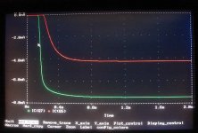
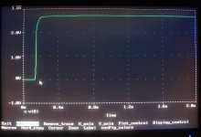
The dodgy screen-shot below shows how the two current-sources start up.
The VAS source reaches 90% of its final value in 267 msec, and the input tail source 472 msec, due to its extra filtering. This appears to show that the THD vs time data for at least the first second should be ignored.
The VAS source reaches 90% of its final value in 267 msec, and the input tail source 472 msec, due to its extra filtering. This appears to show that the THD vs time data for at least the first second should be ignored.
Attachments
stinius said:
IMO it would be nice if John did exactly the same test on the 3xxx that he did on the 4xxx.
Stinius
I think that the real interesting region for the diodes is from 500 micro amps to 10 mA because that is where it will be used and where I am using them.
JPV
But... the important thing is not the VAS current but the voltage the Vbe multiplier gives, and I suspected that it would reach final value much faster. I put a 4x Vbe-multiplier in the VAS collector circuit, with the result seen below. The Vbe-mult output stabilises faster, because of its regulating action, and reaches 90% of final value in only 164 msec.
However- it's more complicated than that. Before the proper VAS current can be established, the input stage must be working enough to turn the VAS itself on, and the input tail source starts up much more slowly. This is getting complicated.
All in all, I think we had better forget the first two seconds or so of my tests, but I think everything after that is valid, and the conclusions in posts #239, #240 are correct about the faster TTrak response.
Attachments
JPV said:The results are close to the data sheet.
Can you make the 3XXX data at a lower peak current like max 10mA to have a correct resolution at 100 micro amp
It seems that resistance starts to influence above 10mA.
JPV
stinius said:
IMO it would be nice if John did exactly the same test on the 3xxx that he did on the 4xxx.
Stinius
I will have to repeat it the same way as for the 4xxx. When all the diodes are wired in series, the voltage resolution available goes down the tubes, hence the "stepped" appearance below 100 uA.
If the data is very close to that of the 4xxx units, I think we could safely say that one wouldn't want to run VAS or multiplier currents less than 1 mA anyway. But, if the data differs, I need to rethink my measurement scheme to be able to accurately log data in the 100 uA to 1 mA region because this might be the region where one gets a tracking tempco with the 3xxx units.
JPV, The 3xxx units arrived today. 4 of each...
John
JPV said:
I think that the real interesting region for the diodes is from 500 micro amps to 10 mA because that is where it will be used and where I am using them.
JPV
Yes if it is the same diode as in the 4xxx I agree, but if it is a MUR120, and the datasheet is correct for the MUR120 I think it would be nice to have the same test as he did on the 3xxx diodes.
Stinius
- Status
- Not open for further replies.
- Home
- Amplifiers
- Solid State
- On Semi ThermalTrak