Although very little power is dissipated in the drivers, the transient part of this experiment is perhaps very sensitive to delta T°.
An initial delta T of 5°C between the driver junction and Vbe transistor junction generates a 20mv increase in Vq bias which will influence a lot the THD reading.
A way to test for this would be to disconnect the power stage instead of switching off the full amplifier and then when cold switch it again on. The increase in power dissipation in the class A driver is way less. This can be done without risks if using a resistive load.
It would be an interesting experiment to rule in or out the influence of the driver in the long term drift which is puzzeling.
JPV
Hi,
they are very close from 1mA to 10mA.
I don't know semi-conductor production but I doubt they can design the devices to give this level of matching.
Surely it must be done by selection and trimming. It seems to indicate that there is some laser trimming going on to arrive at this matching.
Could the parallel buried emitter resistors be used to achieve this?
Why is there a pronounced knee @ 1mA?
Is there a way to determine the effective value of the buried emitter resistor?
Andrew,
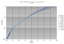
What you see is If/Vf data of internal ThermalTrack MUR diode. It has nothing to do with actual transistor
What you see is If/Vf data of internal ThermalTrack MUR diode. It has nothing to do with actual transistor
AndrewT said:Hi,
they are very close from 1mA to 10mA.
I don't know semi-conductor production but I doubt they can design the devices to give this level of matching.
Surely it must be done by selection and trimming. It seems to indicate that there is some laser trimming going on to arrive at this matching.
Could the parallel buried emitter resistors be used to achieve this?
Why is there a pronounced knee @ 1mA?
Is there a way to determine the effective value of the buried emitter resistor?
The diode is not on the transistor chip, but a separate chip on the same mounting plate, identical for both N and P transistor. What was measured is what I would call a normal dispersion for the forward conduction in a diode.
The real problem is related to the N and P transistors, not having the same Vbe tempco. Repeating the same experiment for N and P Vbe (with temperature as a parameter) would certainly be very interesting.
0.05V was most likely the voltage increment, hence the appearence of a "knee".
syn08 said:
0.05V was most likely the voltage increment, hence the appearence of a "knee".
Actually, the voltage driving the diodes is analog and not "stepped." The appearance of a knee seems to be an artifact in the DSO A/D when sampling values "in the mud" for the selected range. In other words, the data being measured at 1 mA and below is two orders of magnitude below the maximum.
I debated whether to include these values in the plots because they are not nearly as accurate as the rest of the plot. Nonetheless with other list members experimenting with currents below 1 mA, I included it for reference.
If I get a chance, I will measure tempco of Vbe on both PNP and NPN units. But these tests are starting to eat up a lot of time.
On to the temperature testing...
Cheers,
John
jgedde said:If I get a chance, I will measure tempco of Vbe on both PNP and NPN units. But these tests are starting to eat up a lot of time.
On to the temperature testing...
Cheers,
John
Nice John.
Interesting the spread of 50 millivolts at 100mA.
I recommend running the temco's at 6 mA. And, I don't think cold measurements are necessary, unless you plan on building military hardware, eh?
Cheers, John
stinius said:John
I think you have proved that it isn't a MUR120.
Stinius
Remember that I'm testing the 4xxx series not the 3xxx series. My suspicion is that the diodes are different between the two series. The 3xxx series may well use the MUR120 even though the 4xxx doesn't.
Jjohn
jneutron said:
I recommend running the temco's at 6 mA. And, I don't think cold measurements are necessary, unless you plan on building military hardware, eh?
I will be running the full VI curve at temperature (just like the first plot). Tempco isn't consistent with current. By having the full curves available, one will be able to pick a value that yields the tempco he/she desires...
John
They have the theoretical 60mV per decade of current at low current under 1mA. and they have a 120mV per decade at high current which implies resistive effect;
They are very close to the specs which is good.
JPV
They are very close to the specs which is good.
JPV
jgedde said:
Remember that I'm testing the 4xxx series not the 3xxx series. My suspicion is that the diodes are different between the two series. The 3xxx series may well use the MUR120 even though the 4xxx doesn't.
Jjohn
Yes I know we have discussed that before.
To bad that you don't have the 3xxx series, so you could do the same test with them.
Stinius
stinius said:
Yes I know we have discussed that before.
To bad that you don't have the 3xxx series, so you could do the same test with them.
Stinius
Ahhh, but I soon will have them!
JPV is sending me samples of each of the 3xxx series. I will do the same tests as well as give JPV characteristic curves of the transistors for his trouble. That way he can see how well matched they are (or aren't).
All, -25 degC and 0 degC are done. So far it looks like the datasheet is correct... I will post the temperature runs on one plot when I'm done.
John
John
That's good news.
Could you also make plots of the h-parameters?
One with a stabile Uce and varying Ic, and one with stabile Ic and varying Uce.
That would be nice.
Stinius
That's good news.
Could you also make plots of the h-parameters?
One with a stabile Uce and varying Ic, and one with stabile Ic and varying Uce.
That would be nice.
Stinius
JPV said:Although very little power is dissipated in the drivers, the transient part of this experiment is perhaps very sensitive to delta T°.
An initial delta T of 5°C between the driver junction and Vbe transistor junction generates a 20mv increase in Vq bias which will influence a lot the THD reading.
A way to test for this would be to disconnect the power stage instead of switching off the full amplifier and then when cold switch it again on. The increase in power dissipation in the class A driver is way less. This can be done without risks if using a resistive load.
It would be an interesting experiment to rule in or out the influence of the driver in the long term drift which is puzzeling.
JPV
I think there are several things we should bear in mind here.
First, there are numerous things that are stabilizing in the first minutes of an amplifier being turned on. Not only are the drivers warming up some (even a couple C can make a difference), but other transistors as well, including the bias-spreading Vbe multiplier transistor if it is not on the heatsink (not because of its own dissipation, but potentially because of its ambient changing).
In terms of priorities, how the amp sounds or how much distortion it makes in the first few minutes is of relatively little significance. Where we potentially get into trouble is during normal listening where the output stage dissipation is varying due to the changing average power levels. It is this behavior that we seek to track much better.
THD vs time is certainly a neat way to look at the problem, but I'm less enthusiastic about looking at THD vs time after turn-on. I'd much rather look at it after the amplifier has been running at 1/3 power, then perhaps subsequently at a much lower power level that might better expose crossover distortion without creating nearly as much heat. We also must be careful to not be misled by the possibility that the THD will be non-monotonic with temperature under some conditions (under-bias, then over-bias).
I still prefer to view the emitter-to-emitter voltage (whose optimum we should know for a given amplifier) as a function of thermal shock, as when the amplifier cools down after having been run at 1/3 power for an extended period of time. I think this shows most unambiguously how well the ThermalTraks track.
Cheers,
Bob
Bob
I agree, this is what I have stated before, and I don't see the point in why Douglas is looking at the first 20 or 200 seconds.
The amp should be warm to see how good the tracking is.
Stinius
I agree, this is what I have stated before, and I don't see the point in why Douglas is looking at the first 20 or 200 seconds.
The amp should be warm to see how good the tracking is.
Stinius
Bob Cordell said:
I think there are several things we should bear in mind here.
First, there are numerous things that are stabilizing in the first minutes of an amplifier being turned on. Not only are the drivers warming up some (even a couple C can make a difference), but other transistors as well, including the bias-spreading Vbe multiplier transistor if it is not on the heatsink (not because of its own dissipation, but potentially because of its ambient changing).
In terms of priorities, how the amp sounds or how much distortion it makes in the first few minutes is of relatively little significance. Where we potentially get into trouble is during normal listening where the output stage dissipation is varying due to the changing average power levels. It is this behavior that we seek to track much better.
THD vs time is certainly a neat way to look at the problem, but I'm less enthusiastic about looking at THD vs time after turn-on. I'd much rather look at it after the amplifier has been running at 1/3 power, then perhaps subsequently at a much lower power level that might better expose crossover distortion without creating nearly as much heat. We also must be careful to not be misled by the possibility that the THD will be non-monotonic with temperature under some conditions (under-bias, then over-bias).
I still prefer to view the emitter-to-emitter voltage (whose optimum we should know for a given amplifier) as a function of thermal shock, as when the amplifier cools down after having been run at 1/3 power for an extended period of time. I think this shows most unambiguously how well the ThermalTraks track.
Cheers,
Bob
You are certainly right that the emitter to emitter voltage should give an unambiguous way to estimate tracking for a specific amplifier because it is exactly what we try to control.
JPV
jgedde said:
Ahhh, but I soon will have them!
JPV is sending me samples of each of the 3xxx series. I will do the same tests as well as give JPV characteristic curves of the transistors for his trouble. That way he can see how well matched they are (or aren't).
All, -25 degC and 0 degC are done. So far it looks like the datasheet is correct... I will post the temperature runs on one plot when I'm done.
John
They are on their way and you should receive them by tomorrow.
Thanks again for your helping work.
JPV
I wasn't able to finish all the temperature runs today. Still left to do are 100 and 125 degC for the diode, and a tempco determination of the transistors. All will have to wait until tomorrow. So far, it seems the datasheet is very close to reality. By this time tomorrow, we will know all... Then, on to verifying/tweaking the PSPICE model for the diode...
What should I run for base current for the transistor tempco tests? I'd like to keep self-heating to a minimum, but still get a tempco that's at a reasonable value.
Hmmmm. I was just thinking... What if I used another Tek 576 (I have three) to drive the transistor, and use another to look at the diode. Then I'll capture how the diode reacts to load changes in the transistor. In other words, how long it takes to stabilize to a new curve. Just speculating. I have already spent way too much time on this..... 🙂 Oh well, it's for a good cause. So far, you folks have been invaluable to me in sharing your experience and "lessons learned." I guess, even if I do this test, I'll still end up ahead time-wise given that the advice given to me over the past two years has saved me a lot of wasted time...
John
- Status
- Not open for further replies.
- Home
- Amplifiers
- Solid State
- On Semi ThermalTrak