DouglasSelf said:
I'm not sure I understand your question- if the tracking was perfect, the THD wouldn't be plunging or doing anything else. It would be constant, in both the short term and the long term.
Douglas
Hi Doug,
This is nice work and interesting results. I think that before looking at THD vs time, one should look at bias current vs time after startup and after a big thermal transient.
Bias the amp optimally in thermal steady state (e.g., 26 mV across each Re or whatever the right value is for those particular ThermalTraks - it will be less) and then look at the emitter-to-emitter voltage vs time to evaluate the thermal stability in idle from a cold start.
More importantly, one should look at a measure of the output stage bias current immediately after a 1/3 power signal is fed through the amplifier.
This is the sort of thing I illustrated in my MOSFET with EC amplifier paper, where I compared thermal stability of bias for MOSFETs vs BJTs.
Cheers,
Bob
I understand that the THD and bias current should be proportional and this method is an easy and elegant method to measure bias current with a superposed signal. It should be interesting to measure bias time constant while cooling as B. Cordell describes in his paper and bias time constant while heating with the D. Self method. First guess is that the time constant should be the same.
JPV
JPV
JPV said:
OK
When I say perfect tracking I mean perfect perfect equality of temco of Vbias and output transistors. But there is always a thermal delay between them due to size of chip, package, mounting and so on. What I am asking then is: is it not normal to have this dip at the start due to this inevitable delay even if in steady state they track perfectly. It seems to me that the base emitter junction of the Vbias transistor will be cooler than the junction of the output transistor at the start for a short transient time. During that time Vbias will be higher and therefore distortion smaller
My second question is : how do you explain the fact that it has to be way overcompensated to have the TT transistors tracking well. Does thsi mean that the announced temco is wrong?
JPV
Confusion resolved. By "tracking" I meant dynamic as well as static tracking. The question is why we still get a THD dip lasting some 20 seconds when the TTrak diodes are being used. They are supposed to be much faster.
As to why effectively 4 TTrak diodes are needed to match two transistor Vbe's- that is the big question. It's not caused by minor errors in the tempco's- there must be something more serious going on. At the moment I have no idea what. More research needed!
Douglas
Douglas
“The question is why we still get a THD dip lasting some 20 seconds when the TTrak diodes are being used.”
Maybe the temperature is rising faster in the diodes than the temperature in the transistor will be able to take control of the temperature in the diode in the first 20 seconds.
It will always be some delay, but as soon as the temperature of the transistor are the one that is controlling the temperature of the diode (and not the current in the diode) there will be “Tracking”
I therefore don’t think that the first 200 seconds are interesting, but how it will behave when the amp has reach a “working temp”
Regards
Stinius
DouglasSelf said:The question is why we still get a THD dip lasting some 20 seconds when the TTrak diodes are being used. They are supposed to be much faster.Douglas
Diffusivity of the diode attach epoxy,heat capacity of the diode chip, heat capacity of the overmolding epoxy, thermal conductivity of the diode wirebonds. (I'm guessing on the wirebonds, no idea if they used 5 mil aluminum or .7/1/2 mil gold.)
Have you tried monitoring the diode vf after applying a heat pulse to the transistor?
My thinking is your watching the structure time constant. I believe you will find two time constants, one for up and another for down.
Cheers, John
Douglas,
There is one possible explanation for both the 20 second dip at start-up and the fact you need 4 diodes...
It really seem as if there is another tempco at work here... You said you're using an EF type driver stage. I would strongly suspect the tempco of the output stage drivers are coming into play here. They must be carrying their own standing current, and their Vce isn't zero. Therefore, they are dissipating power. Since theta-ja is typically a large number, in 200 seconds, I wouldn't expect any huge change in case temperature, at least not with the finger test. 😀
So, you would have two tempcos that are changing; and not necessarily in sync with each other giving a second order total tempco.
An IR thermograph of your 200 second run would be invaluable as far as verifying whether this is so.
Where are the drivers mounted? On your main heatsink? Or do they have their own? Do they even have/need a sink?
The "finger test" reminds me of the many times I've gotten a DIP tattoo...
I've received an email from Doug Self indicating that he is having a temporary problem posting to DIY, and he will be back as soon as possible. He does not want anyone thinking that he is ignoring their posts.
Cheers,
Bob
Cheers,
Bob
I got two nice surprises today!
1) NJL4281DG was found in stock at Mouser. 5 units arrived today.
2) I got an email from OnSemiconductor syaing samples of the NJL4302DG I ordered several weeks ago had shipped. They weren't expected until March '09!!!
That being the case, I will now be able to run temperature tests of Vf vs If on the integral diodes. I have access to thermal chambers, and a loaner curve tracer (Tek 576) is expected to arrive tomorrow. In case that doesn't pan out, I kluged a VI curve tracer using a sine generator, a servo amplifier, a current probe and an oscilloscope set up for XY mode. The scope can store raw data in CSV format to floppy, so I will be able to plot all of the VI curves at different temperatures on the same graph using Excel and also create a tempco vs current plot using a macro. I'm wondering why I need the curve tracer? perhaps to verify my setup.
I will do current sweeps from 100uA to 1A to get VI curves for temperatures between -25 and +125 degC in 10 deg increments. That way I can verify:
1) The NJL4xxx uses a different diode than the other ThermalTrak units as is my suspicion.
2) The VI curves in the datasheet are right.
3) The diode SPICE model is correct.
4) The NJL4xxx devices match tempco at 7 mA per the datasheet, instead of at a few hundred uA for the 3xxx units.
I need this data to verify my design(s) before I waste too much time and $$$ laying out boards, buying parts, assembling circuits, etc.
I expect to have the 4302s on Monday and run tests soon thereafter. That means I'll have data to share as early as mid next week.
First I will run all 10 units at ambient to get a feel for the variation in Vf between units. If they match closely, I will only run one transistor over temperature. If not, I will wire several (maybe all 10) ThermalTrak diodes in series thus yielding a batch average for VI that will be normalized to one unit by dividing the V data by the number of units in series.
It's difficult to test each one separately at cold because opening the chamber results in severe condensation and the chamber has to equilibrate back to the test temperature. Wiring them all and bringing out the leads is more tedious than I want to deal with.
The VI curve capture happens very quickly (a few ms) with my test rig, so running 1A of test currents won't result in junction temperature changes during the test.
Stay tuned....
John
jgedde said:I'm wondering why I need the curve tracer? perhaps to verify my setup.
Everything you could possibly want to do can be done with a 576..
It is the ultimate machine..
John
Yes, I will. The 4302's arrive monday.
Not one, not two, but THREE Tektronix 576's arrived yesterday. One seems to work perfectly and only needed minor calibration (VI curves with a set of prescision resistors).
I already have the 4281's. It does seem the VI curves of the diodes at ambient have quite a bit of variation between units. 3 are almost excatly the same, 1 is a bit different, and the last is different by almost 50%! I'm debating whether to leave this one out of the test as being out of family. I'll see what the 4302's do and make a decision based on that.
The transistor curves vary quite a bit too.... 3 are exactly the same, 2 are about 75% of the gain of the first three. I'll post everything when I have a completed study...
John
jgedde said:Yes, I will. The 4302's arrive monday.
Not one, not two, but THREE Tektronix 576's arrived yesterday. One seems to work perfectly and only needed minor calibration (VI curves with a set of prescision resistors).
I already have the 4281's. It does seem the VI curves of the diodes at ambient have quite a bit of variation between units. 3 are almost excatly the same, 1 is a bit different, and the last is different by almost 50%! I'm debating whether to leave this one out of the test as being out of family. I'll see what the 4302's do and make a decision based on that.
The transistor curves vary quite a bit too.... 3 are exactly the same, 2 are about 75% of the gain of the first three. I'll post everything when I have a completed study...
John
great work !
Could you test the 3281 familly too.
As you mentionned, the sensitivity to the driver tracking of the bias current in the ouput stage is very large.
if the Vbias transistor tracking the drivers is off by let say 5°C with respect to the driver junction temperature, this is an error of 10mV on 26mV , a huge change in THD reading.
It is perhaps the explanation of the long time constant.
But the 4 diodes needed, there ???
It would be interesting to put thermaltracks in the driver too.
thanks a lot
JPV
Could you test the 3281 familly too.
I didn't plan on using the 3xxx series. That being the case, I don't have any in stock...
I would be happy to test them at the same time as the 4xxx's if someone wants to send some (along with a SASE so I can return them when I'm done). 4-5 of PNP and NPN are a reasonable sample size. My test rig does not require me to solder to the leads, so they will be as good as new when I'm done. I'll run characteristic curves on the transistors as well so the loaner can see how well they are matched.
Email me privately if interested.
Cheers,
john
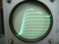
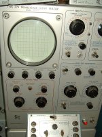
lineup said:beautiful Glen!
is there a built in transistor curve tracer?
It IS a transistor curve tracer. BTW, I made a boo boo. It's a 575.
Attachments
Hi Glen,
I hadn't used one since college - 20 years ago! They're a fun toy! I'm still learning all the things they can do, but I figure I'll soon wonder how I ever got by without one! I don't have to now; as my understanding is I don't have to return them... They're "out of service." One works as new after its calibration was tweaked (it was taken out of service after failing calibration back in '99 and was never adjusted back) and switch contacts were cleaned up. The second works but has a trace so dim that it's unusable - I don't think the CRT is bad. The last also works, but the trace cycles in and out of focus. I'm not sure what would cause that....
One of these days I'll build an actual amp using the ThermalTraks. Right now, I'm still playing games with a complementary input stage... But at least, when I do, I'll have all of the info I need to get it right the first time.
One of the engineers from Jet Propulsion Laboratory I'm currently working with brought a kick-a$$ Tektronix 2 Ghz 4 channel scope with him. That thing does everything! I'm still drooling...
John
G.Kleinschmidt said:
It IS a transistor curve tracer. BTW, I made a boo boo. It's a 575.
That's a boat anchor in beautiful shape for sure! Is it tubed or solid state? When was it made? Have fun with it!
John
These latest posts gave me the incentive to finally dust off my slightly more antique Tek 576.
This bring back memories of the synthesisizer tech who used to
match the differential pairs in my ARP 's using just his
oscilloscope and a "jig" for devices😎 .
OS
- Status
- Not open for further replies.
- Home
- Amplifiers
- Solid State
- On Semi ThermalTrak