roender said:Guys,
You could build RMI-FC100 now 😀
Cheers,
M
Waiting for results of your new version!
"I could sell a couple if anyone in the EU wants a few"
I could be interested.
Can you e-mail me with details.
Thanks,
Brian.
I could be interested.
Can you e-mail me with details.
Thanks,
Brian.
pooge said:
Waiting for results of your new version!
There will not be a new version. If you wait for the version with single ended VAS, sorry but that version now incorporate some Hugh Dean (AKSA) ideas which are not public domain.
Build RMI-FC100, it is a great sounding amplifier!
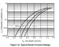
DouglasSelf said:Another attempt to attach Bob's tempco graph.
Great info. I'd like to see another curve for a diode current of 7-8 mA. From the curve, Vbe's tempco is 2.06 mV/degC (expected).
According to OnSemi's curves, 2.1 mV/degC in the ThermalTrak diodes occurs at roughly 7 mA between 25 and 100 degC. Seems like it should be no problem to match tempcos....
John Gedde
Attachments
orjan said:Hi,
I'm interested in in getting a few. You can mail me through the server here.
/örjan
It seems you have the email function turned off, you have to choose "no" on hidden email in the profile options, but this won't really show your address, only activate the e-mail form. You could just send me an email, I've just activated it for mine - didn't realize it was disabled.
stinius said:Is this the "typical forward voltage" for MUR120?
Maybe, if that's what OnSemi buried in the ThermalTrak. The curves I attached are straight from the datasheet for the NJL4281...
How I came up with 7mA is as follows... I blew up the graph until a printed copy gave me a horizontal scale of 1" = 100 mV.
Assuming that it never gets to -25C in my house (hopefully), I considered the two curves at 25C and 100C.
Based on a Vbe tempco of 2.1mV/degC, we get a total delta Vbe of .1575V between 25 and 100C.
Since the scale of my printed copy is 1" per 100 mV, I set my trusty vernier to 1.57" and found where the distance between the 100C and 25C lines was exactly 1.57". It occurred at 7 mA...
John
Yes I see the curve in the datasheet for the NJL3281 as well, but this does not corespond with the MUR120 datasheet.
Stinius
Stinius
stinius said:Yes you are right, it seems that they have changed the diode in the NJL4281 series.
In the NJL3281 / NJL1302 they used the MUR120 series, and the datasheet didn't include the diode curves.
I didn't point that out on purpose. I assumed the 3281 and 4281 were identical except for the 4281 having a different package with higher maximum dissapation: I guess not...
Assuming that the datasheets for both devices have valid diode curves, it would seem that one cannot match tempcos of the 3281 and its diode (except at unusably low currents). With the 4281 you can!
John
I think the curve is wrong.
According to Mr. Hansen the diode is a MUR120.
I don’t know why ONsemi are using a wrong curve, but the Spice model for the transistor is also wrong, see Andy’s site.
Regards
Stinius
According to Mr. Hansen the diode is a MUR120.
I don’t know why ONsemi are using a wrong curve, but the Spice model for the transistor is also wrong, see Andy’s site.
Regards
Stinius
stinius said:I think the curve is wrong.
According to Mr. Hansen the diode is a MUR120.
I don’t know why ONsemi are using a wrong curve, but the Spice model for the transistor is also wrong, see Andy’s site.
Regards
Stinius
You may be right. I'm not familiar with Mr Hansen. Is he an On Semi guy?
Oddly enough, I am able to generate the curves in the 3281 and 4281 datasheets using Andy's SPICE model for the 3281 diode, and OnSemi's model for the 4281 diode. The simulations agree almost exactly with the datasheets. That said, it appears the model match the datasheets.
I also noticed that SPICE models for the diodes of the 3281 and 4281 are quite different. The saturation current value is markedly different which would explain the different VI curves.
I wonder if OnSemi realized the error of their ways and put a diode in the 4281 that's a bit easier to work with...
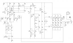
Now I need to get ahold of some actual parts to test since I'm designing a amplifier that assumes the Vbe and diode tempcos for the 4281/4302 are the same at 7 mA.
Assuming the curves are correct, here's my work in progress... Bob Cordell greatly influenced the design...
John Gedde
Attachments
jgedde said:
You may be right. I'm not familiar with Mr Hansen. Is he an On Semi guy?
Oddly enough, I am able to generate the curves in the 3281 and 4281 datasheets using Andy's SPICE model for the 3281 diode, and OnSemi's model for the 4281 diode. The simulations agree almost exactly with the datasheets. That said, it appears the model match the datasheets.
I also noticed that SPICE models for the diodes of the 3281 and 4281 are quite different. The saturation current value is markedly different which would explain the different VI curves.
I wonder if OnSemi realized the error of their ways and put a diode in the 4281 that's a bit easier to work with...
Now I need to get ahold of some actual parts to test since I'm designing a amplifier that assumes the Vbe and diode tempcos for the 4281/4302 are the same at 7 mA.
Assuming the curves are correct, here's my work in progress... Bob Cordell greatly influenced the design...
John Gedde
I am interested to read the results of your tests.
I designed an equivalent output stage ( 3T with thermaltrack) and expect to have the boards very soon. I used the LME49810 as front end to make life easier spending time on the output stage. I implemented a PIC controller to have DC protect, FSOA protect and relay protection control. Later I will certainly "play" with discrete front ends like yours. I am therefore interested to exchange experience with thses toplogies because I believe that the real plus is in the tempco control.
I have a few comments:
First: allthough the diodes are different the tempco variation with current is the same (see my post 82) about 0.2mV/°C per decade of current. It is normal because this is related to basic physics.
Knowing this I wonder why you are saying that currents in the diodes in the order of 0.1 to 1 mA is unusable.
Second, your Vbe multiplier with the diodes in the emitter will see an important interraction between Vbias adjust and tempco adjust. Using diodes in the upper led of the base is making the tempco independent of the Vbias tuning and allows to tune the tempco and Vbias individually.
Using thermaltrack devices as drivers allows to use their diodes in serie with the diodes of the output and track the driver drift too.
Adjusting the drift of the output transistors to keep the condition gmRe =1 instead of (Vq = 26mV ) in temperature is perhaps an important effect with respect to crossover distortion?
JPV
Thanks for the info.
I have some NJL4281 and 4302 devices on order from OnSemi as samples (no distributor seems to have them). I will be testing them over temperature in our thermal chamber at work to verify that they do what I expect. It's no trouble to share my finding with our community.
The Vbe multiplier in the design I posted was just a fleeting idea. It did exactly what you thought it would. I'm trying something new. My new thoughts allow me to adjust Vbias AND tempco. I will post a schematic... Of course, my ideas are contingent on whether the 4000 series ThermalTrak devices act in real life like the datasheet says, and like the SPICE model.
I wouldn't say that currents under 1 mA are unusable, but they provide an unwanted challenge. Especially since Vf will vary more widely as a function of saturation current variability between parts.
It never occurred to me to use the thermalTraks as the predrivers too... That's a great idea!
Thanks,
John Gedde
jgedde said:Thanks for the info.
I have some NJL4281 and 4302 devices on order from OnSemi as samples (no distributor seems to have them). I will be testing them over temperature in our thermal chamber at work to verify that they do what I expect. It's no trouble to share my finding with our community.
The Vbe multiplier in the design I posted was just a fleeting idea. It did exactly what you thought it would. I'm trying something new. My new thoughts allow me to adjust Vbias AND tempco. I will post a schematic... Of course, my ideas are contingent on whether the 4000 series ThermalTrak devices act in real life like the datasheet says, and like the SPICE model.
I wouldn't say that currents under 1 mA are unusable, but they provide an unwanted challenge. Especially since Vf will vary more widely as a function of saturation current variability between parts.
It never occurred to me to use the thermalTraks as the predrivers too... That's a great idea!
Thanks,
John Gedde
It is a fact that the Vbe vs I plot is in real life different from the ideal diode equation. It varies for different types of diodes. I don't know if it varies within a batch.
But I believe that this is irrelevent in our application because we have to tune Vbias at a fixed operating point anyway to minimize distortion.
One can say that at lower currents the impedance of the diode is higher so will be the sensitivity of Vbe on I variation. But this is a second order that can be curred easily by including a small optimal resistor in the collector of the Vbe multiplier transistor.
I am not defending a point but I am trying to learn what would be a major drawback in using the diodes at under 1mA currents.
If there are none, then bleeding the current to adjust the tempco seems to me an nice and easy solution.
JPV
Does anybody know what the stamped codes on the package mean? I'm not talking about the date code below the model number. I'm talking about the codes in the circles on either side of the bolt hole. These are not specified on the data sheet. A number appears in the left circle, and a letter in the right circle. Perhaps the die location??? It would be nice if it indicated measured parameters for matching, but that would be too lucky.
is there a way to discuss this without alerting the fakers to the real codes?pooge said:Does anybody know what the stamped codes on the package mean? I'm not talking about the date code below the model number. I'm talking about the codes in the circles on either side of the bolt hole. These are not specified on the data sheet. A number appears in the left circle, and a letter in the right circle. Perhaps the die location??? It would be nice if it indicated measured parameters for matching, but that would be too lucky.
This is the bit they don't fake. Do we need to make their marketing any easier?
JPV said:
I am interested to read the results of your tests.
I designed an equivalent output stage ( 3T with thermaltrack) and expect to have the boards very soon. I used the LME49810 as front end to make life easier spending time on the output stage. I implemented a PIC controller to have DC protect, FSOA protect and relay protection control. Later I will certainly "play" with discrete front ends like yours. I am therefore interested to exchange experience with thses toplogies because I believe that the real plus is in the tempco control.
I have a few comments:
First: allthough the diodes are different the tempco variation with current is the same (see my post 82) about 0.2mV/°C per decade of current. It is normal because this is related to basic physics.
Knowing this I wonder why you are saying that currents in the diodes in the order of 0.1 to 1 mA is unusable.
Second, your Vbe multiplier with the diodes in the emitter will see an important interraction between Vbias adjust and tempco adjust. Using diodes in the upper led of the base is making the tempco independent of the Vbias tuning and allows to tune the tempco and Vbias individually.
Using thermaltrack devices as drivers allows to use their diodes in serie with the diodes of the output and track the driver drift too.
Adjusting the drift of the output transistors to keep the condition gmRe =1 instead of (Vq = 26mV ) in temperature is perhaps an important effect with respect to crossover distortion?
JPV
I think your approach should work fine, but we do seem to have a different philosophy (or perhaps a different fear of what may go wrong). I like the ThermakTrak diodes in the emitter of the Vbe multiplier because in that location they naturally see more current, putting them in an environment that is a little more similar to that of the output transistors and that for which these fairly large-junction diodes were designed. I do wonder if, for example, their leakage at high temperatures might come into play relative to the current flowing through them. This is just a philosophical comfort level thing for me.
I believe that any interaction between bias level and tempco interaction will be of minimal significance when the diode is used in the emitter of the Vbe multiplier. The temco matching is something that is done once, by design, in the development of the amplifier. Bias trim after that will be a small issue in regard to changing the tempco match. The interaction is there, for sure, but its size must be kept in perspective.
Cheers,
Bob
Bob Cordell said:
I do wonder if, for example, their leakage at high temperatures might come into play relative to the current flowing through them.
Bob,
The diodes are forward biased, so there is no leakage per se.
If you mean the diode saturation current Is (that multiplies the exponential in the diode current equation), then that follows only a T^(3/2) type law, certainly much weaker than the exponential. Therefore, the Is dependency on temperature for forward biased diodes can safely be ignored.
If Is were constant over temp, the temperature coefficient of the diode voltage would be positive at constant Id:
Vd ~= nkT/q * ln(Id/Is)
It's actually the temperature variation of Is that dominates.
Vd ~= nkT/q * ln(Id/Is)
It's actually the temperature variation of Is that dominates.
syn08 said:
Bob,
The diodes are forward biased, so there is no leakage per se.
If you mean the diode saturation current Is (that multiplies the exponential in the diode current equation), then that follows only a T^(3/2) type law, certainly much weaker than the exponential. Therefore, the Is dependency on temperature for forward biased diodes can safely be ignored.
Yes, you are probably right about leakage current not being a concern in a forward-biased diode.
Cheers,
Bob
- Status
- Not open for further replies.
- Home
- Amplifiers
- Solid State
- On Semi ThermalTrak