infinia said:hi Doug
I'm not sure the 2 diodes are equivalent.
From the data sheets
NJL3281D : (0.93-1.1)/(150-25) = -1.36mV/degC
MUR120 series : (1.05-1.25)/(150-25) = -1.6mV/degC
Same Pulse Test: Pulse Width = 300 _s, Duty Cycle _ 2.0%.
Perhaps a 2 Amp diode series would be a better match.
According to post #77 in the other Thermal-Trak thread, it is definitely an MUR120.
Douglas
It really does work ..I use hair dryer and DVM temp probe🙂I've had this problem with ALL the big diode vendors.. It has to do with the kelvin setup oven door and the test equipment.
I tried "poor man's T-trak' method (i.e., to-92 Vbe on a
collector leg) and it works (too good, maybe) very fast
response with smothered with silicone glue.
Thanks for another good idea.
OS
ostripper said:It really does work ..I use hair dryer and DVM temp probe🙂
That'll certainly work..
Potting with stycast was an extreme, but I needed extreme accuracy. The application was paralleling 3 amp rectifiers, about 50 of them. Current sharing across the military temp range was the issue..so I had to worry about across-wafer and inter-wafer matching.
Cheers, John
DouglasSelf said:
I think putting the T-Trak diodes in the Vbe multiplier as shown in your drawing is potentially an elegant way of running them at the lower current.
However your drawing shows shunt resistors across the diodes so the current through them will vary with their temperature. I think there will be fewer unknowns if a fixed 158 uA is put through the diodes. Why does your drawing show four T-Trak diodes? I am assuming an EF stage with two output devices only.
The operating current also needs to increase to at least 10 mA if it is to be part of a VAS,and that will put the base current up.
There also needs to be a way to add on the fixed voltage. (Vfix in Plan B)
What are the "if required" diodes for??
I'll look a bit deeper into this.
Douglas
The shunt resistors are there to tune the tempco. Of course the current will vary like the Vd with temperature but this is second order. The Vd will vary by max 30% for the full range of temperature so will the current but because the tempco varies like the logarithm of the current, this variation of tempco will be negligeable.
I use the same thermaltraks as drivers therefore the two diodes from the drivers + two diodes from the output. The two other diodes " if required" are there to have a total of 6 Vbe drops in Vbias instead of 4 Vbe's. The Vbe multiplier has a minimum Vbias of 4 Vd + Vbe. This is too limit for a Vbias of 4 Vbe's. With 6 Vbe's we are more relaxed in the choice of R1 and R2. In this way the two tempco's are in serie like in your plan B and are independend of the Vbias setting.
JPV
ThermalTrak Design Considerations
Here are a couple of things to bear in mind regarding the use of the ThermalTrak output transistors.
In earlier posts on the other ThermalTrak thread I showed that running about ¼ the current through the diode gave it similar voltage and temperature characteristics to the Vbe of the BJT. This was done specifically for the NJL3281 with BJT and diode currents of 100 mA and 25 mA, respectively. In pointing this out, however, I was not suggesting that the diodes must or should be run at this current level in most ThermalTrak applications. For example, if these diodes were in series with the VAS, running 25 mA through the VAS would often be unattractive. I like to run 10 mA through the VAS.
This all just means that some mechanism of multiplication of the diode temperature coefficient is needed in most applications. In fact, the important thing to keep in mind is the RATIO of TCVbe to TCdiode. Differences in the actual junction voltage are less important and can be accounted for in many ways.
If one runs the BJT at 100 mA and the diode at 10 mA, the TCdiode will be approximately 80% of the TC of the BJT Vbe for the NPN device. I have found that TCVbe is about -2.1 mV/C under these conditions while TC diode is about -1.7 mV/C.
For the PNP BJT, the TC of the diode is about 76% of the TC of the PNP BJT. This appears to be the result of the TCVbe of the PNP device being a bit larger, closer to 2.2 mV/C. The same type ThermalTrak diode is used in the NPN and PNP devices.
Recognizing that it is the RATIO of the BJT and diode TC’s that is important leads to the usefulness of a simple experiment anyone can do in their basement; no ovens or ice buckets required. Diode-connect the BJT and connect it to a 10.6V supply through a 100-ohm 2-watt resistor, so that 100 mA will flow in the BJT. Connect the ThermalTrak diode in the same way, but with a 1k resistor so that 10 mA will flow. Connect a DVM across each junction. Note the junction drops at room temperature. Typical values for the Vbe and diode might be 616 mV and 573 mV for the NJL3281 under these conditions. The typical value for the NJL1302 PNP device might be about 598 mV.
Now take your heat gun and heat up the transistor (it is just laying on the bench, no heat sink). Heat it until the BJT junction voltage drops by about 100 to 120 mV. After about 5 seconds, start logging the two junction drops at intervals of about every 10 mV as the device cools on its own. The resulting data will show you the ratio of the junction TC’s for the device you are using.
A conceptually simple way to build the bias spreader for a ThermalTrak stage is to employ two Vbe multipiers in series. The first is the main temperature compensator and it has two ThermalTrak diodes in series with the emitter of the Vbe multiplier transistor, one from the NPN output and one from the PNP output. The multiplier transistor is not mounted on a heat sink and the presence of its Vbe dilutes the TC of the diode TC’s to about 67%. On the other hand, the ThermalTrak diode TC’s needed to be enhanced by an average of a factor of about 1/0.78 = 1.28. The Vbe multiplier thus should be set to have a multiplication factor of about 1.91. This can be altered depending on whether the designer wants the output transistors over-compensated or under-compensated. The output transistors are now taken care of.
Obviously, there are useful variations of this that may employ more than two ThermalTrak diodes for amplifiers employing paralleled output pairs.
The second Vbe multiplier takes care of the bias spreading needed by the drivers and pre-drivers (if used) and any mop-up bias spreading voltage needed, and probably the bias setting pot. Recognizing that most amplifiers have bias spreaders that ignore the temperature of the drivers (a potential shortcoming), the second Vbe multiplier transistor also need not be connected to any heat sink or heat source. If desired, of course, it could be bolted to one of the drivers to take account of the warm-up heating of the driver. Many possibilities exist.
Finally, if you play your cards right, you can usually get away with a single Vbe multiplier for the whole function, although it might require an additional diode or two. The cost savings will be fairly trivial, however.
Cheers,
Bob
On further reflection I think I made an error in my post above. I said that the presence of the Vbe multiplier transistor Vbe diluted the TC of the ThermalTrak diodes to about 67%, and then went on to say that this dilution should be taken into account in setting the multiplication ratio of the Vbe multiplier. I think this is wrong. I think the ratio only needs to be 1.28:1.
Cheers,
Bob
Cheers,
Bob
Re: ThermalTrak Design Considerations
I do not understand the 67%; could you make a drawing.
In your system, can you tune independently the tempco and Vbias or do you have an interraction.
The simple system that I explained above I believe can do it.
This in my opinion is interesting because to take into account real life elements it is possible to minimize distortion at room temperature by Vbias adjust and then minimize distortion at maximum operating temperature by adjusting the tempco of the diodes tuning their // resistor. By using a thermaltraks as drivers, you can use 4 diodes and track the drivers too.
JPV
Bob Cordell said:Here are a couple of things to bear in mind regarding the use of the ThermalTrak output transistors.
In earlier posts on the other ThermalTrak thread I showed that running about ¼ the current through the diode gave it similar voltage and temperature characteristics to the Vbe of the BJT. This was done specifically for the NJL3281 with BJT and diode currents of 100 mA and 25 mA, respectively. In pointing this out, however, I was not suggesting that the diodes must or should be run at this current level in most ThermalTrak applications. For example, if these diodes were in series with the VAS, running 25 mA through the VAS would often be unattractive. I like to run 10 mA through the VAS.
This all just means that some mechanism of multiplication of the diode temperature coefficient is needed in most applications. In fact, the important thing to keep in mind is the RATIO of TCVbe to TCdiode. Differences in the actual junction voltage are less important and can be accounted for in many ways.
If one runs the BJT at 100 mA and the diode at 10 mA, the TCdiode will be approximately 80% of the TC of the BJT Vbe for the NPN device. I have found that TCVbe is about -2.1 mV/C under these conditions while TC diode is about -1.7 mV/C.
For the PNP BJT, the TC of the diode is about 76% of the TC of the PNP BJT. This appears to be the result of the TCVbe of the PNP device being a bit larger, closer to 2.2 mV/C. The same type ThermalTrak diode is used in the NPN and PNP devices.
Recognizing that it is the RATIO of the BJT and diode TC’s that is important leads to the usefulness of a simple experiment anyone can do in their basement; no ovens or ice buckets required. Diode-connect the BJT and connect it to a 10.6V supply through a 100-ohm 2-watt resistor, so that 100 mA will flow in the BJT. Connect the ThermalTrak diode in the same way, but with a 1k resistor so that 10 mA will flow. Connect a DVM across each junction. Note the junction drops at room temperature. Typical values for the Vbe and diode might be 616 mV and 573 mV for the NJL3281 under these conditions. The typical value for the NJL1302 PNP device might be about 598 mV.
Now take your heat gun and heat up the transistor (it is just laying on the bench, no heat sink). Heat it until the BJT junction voltage drops by about 100 to 120 mV. After about 5 seconds, start logging the two junction drops at intervals of about every 10 mV as the device cools on its own. The resulting data will show you the ratio of the junction TC’s for the device you are using.
A conceptually simple way to build the bias spreader for a ThermalTrak stage is to employ two Vbe multipiers in series. The first is the main temperature compensator and it has two ThermalTrak diodes in series with the emitter of the Vbe multiplier transistor, one from the NPN output and one from the PNP output. The multiplier transistor is not mounted on a heat sink and the presence of its Vbe dilutes the TC of the diode TC’s to about 67%. On the other hand, the ThermalTrak diode TC’s needed to be enhanced by an average of a factor of about 1/0.78 = 1.28. The Vbe multiplier thus should be set to have a multiplication factor of about 1.91. This can be altered depending on whether the designer wants the output transistors over-compensated or under-compensated. The output transistors are now taken care of.
Obviously, there are useful variations of this that may employ more than two ThermalTrak diodes for amplifiers employing paralleled output pairs.
The second Vbe multiplier takes care of the bias spreading needed by the drivers and pre-drivers (if used) and any mop-up bias spreading voltage needed, and probably the bias setting pot. Recognizing that most amplifiers have bias spreaders that ignore the temperature of the drivers (a potential shortcoming), the second Vbe multiplier transistor also need not be connected to any heat sink or heat source. If desired, of course, it could be bolted to one of the drivers to take account of the warm-up heating of the driver. Many possibilities exist.
Finally, if you play your cards right, you can usually get away with a single Vbe multiplier for the whole function, although it might require an additional diode or two. The cost savings will be fairly trivial, however.
Cheers,
Bob
I do not understand the 67%; could you make a drawing.
In your system, can you tune independently the tempco and Vbias or do you have an interraction.
The simple system that I explained above I believe can do it.
This in my opinion is interesting because to take into account real life elements it is possible to minimize distortion at room temperature by Vbias adjust and then minimize distortion at maximum operating temperature by adjusting the tempco of the diodes tuning their // resistor. By using a thermaltraks as drivers, you can use 4 diodes and track the drivers too.
JPV
Re: Re: ThermalTrak Design Considerations
I don't have time to make a drawing right now, but just visualize a conventional Vbe multiplier, except that you place two diodes in series with the emitter of the transistor. The multiplier is now multiplying THREE Vbe's. Because two of them track output transistor junction temperature and one does not, that is where the errant mention of two-thirds came from.
Your circuit should work fine, but I prefer to run nearly all of the VAS standing current throught the ThermalTrak diodes, which is what happens when you place them in the emitter of the Vbe multiplier transistor.
I'm sure the circuit has some interaction between setting tempco and setting bias. I'm sure most circuits would have some such interaction. This balance is something one would only do once, in my opinion. Thereafter, one would use fixed resistors in the Vbe multiplier with the ThermalTrak diodes in it.
Cheers,
Bob
JPV said:
I do not understand the 67%; could you make a drawing.
In your system, can you tune independently the tempco and Vbias or do you have an interraction.
The simple system that I explained above I believe can do it.
This in my opinion is interesting because to take into account real life elements it is possible to minimize distortion at room temperature by Vbias adjust and then minimize distortion at maximum operating temperature by adjusting the tempco of the diodes tuning their // resistor. By using a thermaltraks as drivers, you can use 4 diodes and track the drivers too.
JPV
I don't have time to make a drawing right now, but just visualize a conventional Vbe multiplier, except that you place two diodes in series with the emitter of the transistor. The multiplier is now multiplying THREE Vbe's. Because two of them track output transistor junction temperature and one does not, that is where the errant mention of two-thirds came from.
Your circuit should work fine, but I prefer to run nearly all of the VAS standing current throught the ThermalTrak diodes, which is what happens when you place them in the emitter of the Vbe multiplier transistor.
I'm sure the circuit has some interaction between setting tempco and setting bias. I'm sure most circuits would have some such interaction. This balance is something one would only do once, in my opinion. Thereafter, one would use fixed resistors in the Vbe multiplier with the ThermalTrak diodes in it.
Cheers,
Bob
DouglasSelf said:
I have never tried to run a VAS at 25 mA,and I fear the linearity might be worse. Certainly TO-92 transistors will get too hot for amplifiers above 100W/8R, which is a problem as the bigger devices tend to have less beta. A VAS buffer may be needed.
Hi.
One technique I’ve used in designs requiring a high VAS standing current that works well without sacrificing linearity is to use parallel devices at 10mA each.
You can then use a large amount of emitter degeneration on each VAS transistor without sacrificing (miller) loop gain.
Cheers,
Glen
Re: Re: Re: ThermalTrak Design Considerations
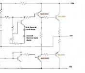
Hello
Maby I draw it a bit too simplified, but it could look like that with an EF output stage.
Gaetan
Bob Cordell said:
I don't have time to make a drawing right now, but just visualize a conventional Vbe multiplier, except that you place two diodes in series with the emitter of the transistor. The multiplier is now multiplying THREE Vbe's. Because two of them track output transistor junction temperature and one does not, that is where the errant mention of two-thirds came from.
Cheers,
Bob
Hello
Maby I draw it a bit too simplified, but it could look like that with an EF output stage.
Gaetan
Attachments
Re: Re: Re: Re: ThermalTrak Design Considerations
Hi Gaetan,
Yes, this is exactly right for the Vbe multiplier that is responsible for temperature compensation/tracking.
Depending on details, one may want to incorporate a second Vbe multiplier in series with this one to provide additional bias spread that is not tracking the output transistors. However, in the case here of a Double rather than a Triple, this single Vbe multiplier may do well enough.
There are a great many possibilities.
Cheers,
Bob
gaetan8888 said:
Hello
Maby I draw it a bit too simplified, but it could look like that with an EF output stage.
Gaetan
Hi Gaetan,
Yes, this is exactly right for the Vbe multiplier that is responsible for temperature compensation/tracking.
Depending on details, one may want to incorporate a second Vbe multiplier in series with this one to provide additional bias spread that is not tracking the output transistors. However, in the case here of a Double rather than a Triple, this single Vbe multiplier may do well enough.
There are a great many possibilities.
Cheers,
Bob
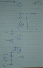
Here is a much simpler thermal-track scheme that I just thought up.
Just a single thermal-track is used, but it biases the VAS constant current source.
We then adjust Rtc to dial in any temperature compensation coefficient required (Rtc/68) and trim the output stage bias current with Vb.
Cheers,
Glen
Just a single thermal-track is used, but it biases the VAS constant current source.
We then adjust Rtc to dial in any temperature compensation coefficient required (Rtc/68) and trim the output stage bias current with Vb.
Cheers,
Glen
Attachments
Re: Re: Re: Re: Re: ThermalTrak Design Considerations
Alternatively, you could do this, requires just an extra voltage divider, not a whole vbe multiplier circuit:
http://www.diyaudio.com/forums/showthread.php?postid=1646364#post1646364
The lower pot should probably be a fixed divider.
Bob Cordell said:
Hi Gaetan,
Yes, this is exactly right for the Vbe multiplier that is responsible for temperature compensation/tracking.
Depending on details, one may want to incorporate a second Vbe multiplier in series with this one to provide additional bias spread that is not tracking the output transistors. However, in the case here of a Double rather than a Triple, this single Vbe multiplier may do well enough.
There are a great many possibilities.
Cheers,
Bob
Alternatively, you could do this, requires just an extra voltage divider, not a whole vbe multiplier circuit:
http://www.diyaudio.com/forums/showthread.php?postid=1646364#post1646364
The lower pot should probably be a fixed divider.
G.Kleinschmidt said:Here is a much simpler thermal-track scheme that I just thought up.
Just a single thermal-track is used, but it biases the VAS constant current source.
We then adjust Rtc to dial in any temperature compensation coefficient required (Rtc/68) and trim the output stage bias current with Vb.
Cheers,
Glen
Interesting, but I see one potential drawback - bias will drop when clipping as average VAS current decreses in that situation. It seems like current drawn by the next stage will decrease the bias too, more decrease with higher output current.
This assumes the cap you drew is relatively large.
"May do well enough", "may do not well enough", where are your calculations fellow engineers?
When I worked on the problem, I preferred to use heating, let me repeat, heating transistors on the same heatsink. Externally heating and directly sensing devices. With zero phase shift between heating and measuring. This way I managed to get stable and predictable crossover processes. But the funny story is, as the result of such achievement, I concluded that the whole idea of complementary emitter follower is stupid. No, please let me repeat: it is stupid.
When I worked on the problem, I preferred to use heating, let me repeat, heating transistors on the same heatsink. Externally heating and directly sensing devices. With zero phase shift between heating and measuring. This way I managed to get stable and predictable crossover processes. But the funny story is, as the result of such achievement, I concluded that the whole idea of complementary emitter follower is stupid. No, please let me repeat: it is stupid.
megajocke said:
Interesting, but I see one potential drawback - bias will drop when clipping as average VAS current decreses in that situation. It seems like current drawn by the next stage will decrease the bias too, more decrease with higher output current.
This assumes the cap you drew is relatively large.
Yeah, you definately wouldn't want to try it with anything less than a triple EF output stage and there is nothing much you can do to (besides a big cap) to prevent the bias dropping when clipping.
Cheers,
Glen
Re: Re: Re: Re: Re: Re: ThermalTrak Design Considerations
All things are possible, but bear in mind that a "whole Vbe multiplier circuit" is little more than a $0.05 transistor and two resistors. I'm sure it can be made to work, but I am not crazy about approaches that steal bias current away from the ThermalTrak diodes to make things right.
Cheers,
Bob
megajocke said:
Alternatively, you could do this, requires just an extra voltage divider, not a whole vbe multiplier circuit:
http://www.diyaudio.com/forums/showthread.php?postid=1646364#post1646364
The lower pot should probably be a fixed divider.
All things are possible, but bear in mind that a "whole Vbe multiplier circuit" is little more than a $0.05 transistor and two resistors. I'm sure it can be made to work, but I am not crazy about approaches that steal bias current away from the ThermalTrak diodes to make things right.
Cheers,
Bob
If that is what you want you can take one resistor/pot from the base to the anodes of thermaltraks and one from the base to their cathode. Remove the buffer if you want full VAS current through diodes/vbe multiplier.
- Status
- Not open for further replies.
- Home
- Amplifiers
- Solid State
- On Semi ThermalTrak