Re: i know nothing,but
If you can remind me when & where the Margan article appeared, I'll take a look.
Douglas
albin said:what about Erik Margans use of diodes to control Iq?dare I ask Douglas.I built his test circuit but replaced the bias transistor with two diodes in series.they worked, I thought, but I could be wrong,
Please ignore or not
regards
max albin
If you can remind me when & where the Margan article appeared, I'll take a look.
Douglas
megajocke said:But if we put the diodes in the upper leg of the Vbe multiplier base circuit (like leach) their tempco won't be multiplied. And 160µA sounds like a reasonable current to have flowing there, just use a buffer for the Vbe multiplier transistor and it will have enough beta to be stable with vas current.
Or is your worry that when doing this the tempco of the vbe multiplier transistor part will be too high, decreasing idle current with increased ambient/driver temperature? But this should be pretty stable.
edit:
"But this should be pretty stable." was referring to the ambient temperature which won't vary as much as output transistor case temperature.
Hi
I'm not saying it wouldn't work, though you are right that at least a two-transistor Vbe multiplier would be needed to avoid base current issues.
My main purpose was to see if we agree that the conceptual circuit is what we should be aiming for.
Douglas
DouglasSelf said:
Hi JPV, sorry I couldn't get back to you yesterday.
My first attempt at applying the ThermalTraks was to assume that the diodes would be used to attempt to directly cancel the transistor Vbe voltages,which means running the diodes at 25 mA (for transistor Ic=100mA) and accepting that the tempco would not match exactly. The compensation should, I think, still be much better than conventional methods but it is certainly not theoretically perfect. This is the approach I used in the attached circuit, which I think of as Plan A. I have never tried to run a VAS at 25 mA,and I fear the linearity might be worse. Certainly TO-92 transistors will get too hot for amplifiers above 100W/8R, which is a problem as the bigger devices tend to have less beta. A VAS buffer may be needed.
I accept what you say about increasing diode tempco's by reducing the current. I have just reread RA Pease's thoughts on it; http://www.national.com/rap/Story/vbe.html and and he certainly quotes - 0.2mV/°C per decade decrease of current. Our diodes have a tempco of 1.7 mV/degC and the transistor Vbe has a tempco of 2.14 mV/degC at 25mA (Bob Cordell's figures) so diode tempco needs to be increased by 0.44 mV/degC. The diode current therefore needs to reduced by 2.2 decades, or 158 times. That gives us a diode current of 158 uA. (not a typo) This is much too low for a VAS operating current so we need a circuit that will replicate the diode voltage at much greater current.
The lower current is clearly not going to give us enough diode voltage to cancel the transistor Vbe's directly. However we cannot use a conventional multiplier circuit as in multiplying the voltage we also multiply the tempco. What is needed is to add a fixed voltage to the diode voltage. If we assume we are using an EF type 2 output, then we also need compensation for the driver Vbe's which can be done with a conventional Vbe multiplier circuit, as used in Plan A.
Another point is that a diode current of 158 uA is quite small, and whatever circuitry we use will have to have its base currents looked at carefully if it is not be inaccurate.
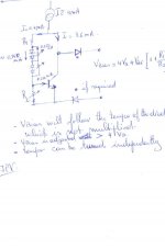
It therefore looks as if we need a system like that shown conceptually in the second diagram. Vdriver compensates the driver Vbe's. The fixed voltage is derived from black box called Vfix, and the diode voltages are replicated by a black box called Vdiodes. I am calling this approach Plan B. It should give much better compensation than Plan A, but it's going to take a bit of designing...
What do people think?
I'm not sure if I can put two pictures in one post, but I'm about to find out.
Douglas
Your plan B is of course one good answer but as you said it requires a bit of design (which should not afraid diy'ers when I see all the troubles they go through with sophisticated front ends and error corrections !)
But as mentionned, the topology used by Leach should work like explained in the attachement.
What do you think?
Jean-Pierre
ostripper said:
I think you have described most HT receivers on the market
today!(thank god they have thermal cutoff in their protection circuits) .
The idea of putting the Vbe on the collector leg is cool😎
I'll try it.(poor mans way of getting thermaltrak performance)
BTW.. Thanks,Mr. Self, for the BEST book on amplifier design
and for the "blameless design" which with proper layout
and device selection is one killer amp. I look forward to the latest
edition (I only have Ed.3).
Thanks,OS
Thank you for your kind words!
You do realise the current edition is the 4th edition?
Switching briefly to the problem of practical tests, it would be good if we could agree on a way to do them.
The method I have used in the past to plot output stage bias conditions is to deliberately underbias the amplifier by a modest amount, but enough to make sure it is always underbiased. I have used a bias setting that gave about 0.02% THD with a peak responding measurement mode. The AP System-1 can plot THD against time and this effectively gives a plot of bias conditions against time. (see p379 in the Fourth edition of the Audio Power Amplifier book)
Do people agree that this is a valid method?
Douglas
What is the dV/dI (maybe called dynamic resistance or something) of the diodes at that current?
If it is big then diverting current with resistors will decrease the temperature coefficient instead of increasing it!
I didn't do the calculations though so I'm not saying it won't work, but have it in mind.
If it is big then diverting current with resistors will decrease the temperature coefficient instead of increasing it!
I didn't do the calculations though so I'm not saying it won't work, but have it in mind.
On Semi Thermal Trak
From the article Silcion Chip Sept 08
http://www.siliconchip.com.au/cms/A_110797/printArticle.html
the voltage accross the diodes appears to be .5v which is more of the schottky performance. Also,see related performance graphs for a further statrting point in the discussion, from some one who has built a unit and measured the responses as well a having a dose of the big brown smoke, yes the journalists not myself.
alfred
Hey guys! I thought the thermaltrak devices were designed
to allow for simpler layouts. Post 99 onwards shows
an exercise in more advanced tempco circuit considerations.
The ultra LD amp seems to be a classic "blameless" with
T-trak diodes used as Vbias (simple).
Looking at the board layout would this not add alot of
extra traces/capacitances to the design? (oscillations/puffs
of brown smoke..? drugs or blown op's??).
I,m using 2 pair NJW0281/0302 (which is equivalant to these
t-traks minus the diodes) with short 4cm leads to the Vbe.
(like the aska lifeforce)...rock stable.
The T-trak OP stage using the Leach Vbe seems to be the best
way to go.
BTW.. Mr. self , If I was to give back to the community an amp
based heavily on your "Blameless" design would you approve.?
OS
megajocke said:What is the dV/dI (maybe called dynamic resistance or something) of the diodes at that current?
If it is big then diverting current with resistors will decrease the temperature coefficient instead of increasing it!
I didn't do the calculations though so I'm not saying it won't work, but have it in mind.
No
operating the diode at another current will change the Vd of course and more if the dV/dI is high at the operating point. But at a fixed operating current in the diode this will be a fixed Vd for which the Vbe multiplier will be adjusted.
Now, if the temperature changes, the Vd will drift for the tempco at that current and so the Vbias.
Of course the Vd changing with temperature, the current in the diode changes so the tempco but this is a negligible effect because the proportionnal change in current in the diode due to Vd drift is equal to that drift. This is about 30% for the full range of temperature. This is a low change in tempco because the tempco changes logaritmically with the current.
JPV
vDouglasSelf said:Switching briefly to the problem of practical tests, it would be good if we could agree on a way to do them.
The method I have used in the past to plot output stage bias conditions is to deliberately underbias the amplifier by a modest amount, but enough to make sure it is always underbiased. I have used a bias setting that gave about 0.02% THD with a peak responding measurement mode. The AP System-1 can plot THD against time and this effectively gives a plot of bias conditions against time. (see p379 in the Fourth edition of the Audio Power Amplifier book)
Do people agree that this is a valid method?
Douglas
Are you saying that this graph was made not by measuring the voltage change with current source changes but by measuring the THD change and that it gives the same result.
As a side note, on the page 377 you are refering figures non existing ( 6.14).
JPV
JPV said:
v
Are you saying that this graph was made not by measuring the voltage change with current source changes but by measuring the THD change and that it gives the same result.
As a side note, on the page 377 you are refering figures non existing ( 6.14).
JPV
Yes, Fig 13.34 measures THD against time. I think it directly measures what we are interested in- the bias in the output stage, as the distortion due to the under-biasing swamps all other distortions.
Fig 6.14 should be Fig 6.17 in Chapter 6. Typo noted.
Douglas
JPV said:
Your plan B is of course one good answer but as you said it requires a bit of design (which should not afraid diy'ers when I see all the troubles they go through with sophisticated front ends and error corrections !)
But as mentionned, the topology used by Leach should work like explained in the attachement.
What do you think?
Jean-Pierre
I think putting the T-Trak diodes in the Vbe multiplier as shown in your drawing is potentially an elegant way of running them at the lower current.
However your drawing shows shunt resistors across the diodes so the current through them will vary with their temperature. I think there will be fewer unknowns if a fixed 158 uA is put through the diodes. Why does your drawing show four T-Trak diodes? I am assuming an EF stage with two output devices only.
The operating current also needs to increase to at least 10 mA if it is to be part of a VAS,and that will put the base current up.
There also needs to be a way to add on the fixed voltage. (Vfix in Plan B)
What are the "if required" diodes for??
I'll look a bit deeper into this.
Douglas
ostripper said:Hey guys! I thought the thermaltrak devices were designed
to allow for simpler layouts. Post 99 onwards shows
an exercise in more advanced tempco circuit considerations.
The ultra LD amp seems to be a classic "blameless" with
T-trak diodes used as Vbias (simple).
Looking at the board layout would this not add alot of
extra traces/capacitances to the design? (oscillations/puffs
of brown smoke..? drugs or blown op's??).
I,m using 2 pair NJW0281/0302 (which is equivalant to these
t-traks minus the diodes) with short 4cm leads to the Vbe.
(like the aska lifeforce)...rock stable.
The T-trak OP stage using the Leach Vbe seems to be the best
way to go.
BTW.. Mr. self , If I was to give back to the community an amp
based heavily on your "Blameless" design would you approve.?
OS
Well, you wouldn't be the first...
http://www.siliconchip.com.au/cms/A_110797/printArticle.html
is a copy of the Blameless design, carefully including a mistake I made. (putting a resistor in the input tail- bad move)
I thought I'd see what PSPICE makes of the MUR120 diode properties as the current varies. Using the standard MUR120 model from the library, this is what came out:
IDiode Vfwd Tempco Vfix
mA mV mV/degC mV
25 681.0 1.62 0 ref
10 634.3 1.77
5 602 1.88
2 566.4 2.00
1 543.7 2.07
0.5 523.5 2.14 157.5
0.2 498.3 2.23
0.158 492.2 2.25 188.8
0.1 479.8 2.29 201.2
The tempco at 25mA is 1.62 mV/degC which is close to Bob's value of 1.7 mV/degC. That's reassuring.
However, we get the desired tempco of 2.14 mV/degC at 500uA, not 158uA, so we need to be a bit flexible in our circuit design.
The added Vfix voltage needed to match the transistor Vbe's comes out as 157.5mV.
So there we are. As a first attempt try Idiode = 500uA and Vfix=157.5mV for circuit design
Douglas
Hmmm. It looks as though the formatting of that table has gone to hell on posting. Picture of table attached.
Attachments
hi Doug
I'm not sure the 2 diodes are equivalent.
From the data sheets
NJL3281D : (0.93-1.1)/(150-25) = -1.36mV/degC
MUR120 series : (1.05-1.25)/(150-25) = -1.6mV/degC
Same Pulse Test: Pulse Width = 300 _s, Duty Cycle _ 2.0%.
Perhaps a 2 Amp diode series would be a better match.
I'm not sure the 2 diodes are equivalent.
From the data sheets
NJL3281D : (0.93-1.1)/(150-25) = -1.36mV/degC
MUR120 series : (1.05-1.25)/(150-25) = -1.6mV/degC
Same Pulse Test: Pulse Width = 300 _s, Duty Cycle _ 2.0%.
Perhaps a 2 Amp diode series would be a better match.
infinia said:Same Pulse Test: Pulse Width = 300 _s, Duty Cycle _ 2.0%.
Ohno...pulse test??
You've no idea how many elevated temp diode vf tests have been done with bad equipment.
Here all along I've been thinking you guys are talking about dc values..
Sigh...
You have to do DC, or you may be working off garbage data.
I've had this problem with ALL the big diode vendors.. It has to do with the kelvin setup oven door and the test equipment.
Positive tempco's, negative tempco's, zero...what a mess. I ended up potting diodes 3 at a time into an aluminum case with stycast 2851kt, and include a pair of thermocouples.
Cheers, John
Not really using this data for absolute value, just to compare if diodes are equivalent size wise.
dynamic test done with the same vendor same way s/b ok just to cross check.
dynamic test done with the same vendor same way s/b ok just to cross check.
Well, you wouldn't be the first...
yeah , I know, many amps here are based on your work.
(I won't mention names,just look around)
On the subject of T-trak type devices Sanken has a similar
offering..
http://www.sanken-ele.co.jp/en/prod/semicon/pdf/data_std01n_pe.pdf
As I've actually seen these devices in consumer products
I know they don't have any TempCo issues. Diodes are
better matched to device gain.I know you hate darlingtons
but these sound really good in general use. (not as good
as my blameless)
A very elegant solution to "cram' 7 amps onto 1 board as
is intended for integrated devices like these.
OS
My point is the test may be corrupt.
At the time (back when dino's roamed the earth), the big players all published temp data in their catalogs. It is easy enough to check the 125 C and 25 C curves, and calculate the deltav/deltat for multiple currents. The problem was, the high temp vf data was no good.
The end result was tempcos that were not correctly calculated.
That's why I recommend actual measurement at DC. Designing all kinds of circuitry around a tempco that may not be realistic is just beggin for problems.
Unitrode, Moto, TI, IR...they all had corrupt temp data in their sheets..problem was, the darn test hardware worked perfectly at room temperature...
The assumption that your 150 C data is correct is a suspect assumption.
Cheers, John
- Status
- Not open for further replies.
- Home
- Amplifiers
- Solid State
- On Semi ThermalTrak