Unloaded Supply Voltage: 27.6
Loaded Supply Voltage: 26.1
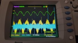
Loaded Supply Ripple: Approximately 15mV pp
Power supply rpple is about the same but the shape is a little different.
Hmm - wondering about the long term effects of 26 Volts on 25 WVDC caps. Some are probably more robust than others.
Well, both the original voltage and the higher voltage are too much for 25WVDC caps. For hobby usage, 35WVDC is Ok, and what many would use. For commercial use, 50WVDC would be specified.
That's what I was thinking. I am waiting for some of prasi's LT4320 CRC boards which, with 18 volt trafo windings, suggests 35WVDC caps at a minimum.
Hmm - wondering about the long term effects of 26 Volts on 25 WVDC caps. Some are probably more robust than others.
My secondaries are 19V not 18V.
So you will not have 26V
That's what I was thinking. I am waiting for some of prasi's LT4320 CRC boards which, with 18 volt trafo windings, suggests 35WVDC caps at a minimum.
I don't quite understand this statement.
You can install 35V caps in the pcb you already have.
Why do you need to wait for a new board?
Or you could purchase another universal psu or you could buy the board I have which is better than the universal psu.
Last edited:
and we know that they're cool
I'm mostly interested can you hear some difference?
Not yet listened, but I will get there.
I think where this will be most audible is in a Class AB amp running some sissy caps in the conventional manner.
In class A we decouple a little bit from the rectifiers because of the RC in our power supply, the Amp is mostly seeing the caps at the output, and the dynamic current draw is far less significant than Class AB.
Having said that even if the improvement is say 5% for Class A, compared with 20% on Class AB, it's probably worth having.
At this point in time that is mostly a philosophical discussion.
I will try to do a listening test very soon, today or tomorrow.
Just some very rough math.
I have a 0.24 V drop across the power supply resistors, that's around 2A across the resistors (around 0.12 Ohms).
If we add that back on to the loaded voltages we get:
Passive Rectifier
Unloaded Supply Voltage: 26.4 V
2A Loaded Supply Voltage: 24.5 V + 0.24 = 24.74
26.4 - 24.74 = 1.66V loss
1.66/2 = 0.83 Ohms
Active rectifier
Unloaded Supply Voltage: 27.6
2A Loaded Supply Voltage: 26.1 + 0.24 = 26.34
(27.6 - 26.34) = 1.26V loss
1.26/2= 0.63 Ohms
Apparent dc output impedance at 2A is a little better with active as expected.
Last edited:
I don't quite understand this statement.
You can install 35V caps in the pcb you already have.
Why do you need to wait for a new board?
Or you could purchase another universal psu or you could buy the board I have which is better than the universal psu.
I don't have any extra pcbs for my new F7 build lying around, so I wanted to go straight to prasi's version which incorporates CRC with the LT4320. I think this is a cleaner solution. Unfortunatly, prasi's boards are stuck in shipping limbo from India due to the pandemic. So I may want to look at alternatives for now.
Where did your boards come from?
The PSU boards I currently use were designed by me, JPS did the pcb design for me, then I got them manufactured. They have a much better ground plane, allow for more caps to be installed, and have the ground lift thermistor on the board. On top of that the mounting holes are the same as the diyaudio psu store boards, so you can throw them straight in.
I will be releasing something even better very soon if you can wait. Better in the sense it features many options.
I will be releasing something even better very soon if you can wait. Better in the sense it features many options.
Last edited:
That would great. I was thinking about doing my own since all the options I have seen seem to have a lot of compromises. A take no prisoners PSU design would be welcome. Active rectification, tons of capacitance, ground lift, over current protection, small form factor, and other options. 😀
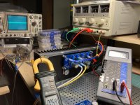
Finally some progress...
Heat soaking one channel with bench power supply - idling at about 1.25 Amps (~60 Watts total) - heatsink is warm but not too hot. MOSFET bodies around 140 F. Offset is very stable. Input shorted, no load.
Next steps - hook up dummy load, do some signal measurements and play with input FET source pot, positive feedback, etc.
Attachments
Just some very rough math.
I have a 0.24 V drop across the power supply resistors, that's around 2A across the resistors (around 0.12 Ohms).
If we add that back on to the loaded voltages we get:
Passive Rectifier
Unloaded Supply Voltage: 26.4 V
2A Loaded Supply Voltage: 24.5 V + 0.24 = 24.74
26.4 - 24.74 = 1.66V loss
1.66/2 = 0.83 Ohms
Active rectifier
Unloaded Supply Voltage: 27.6
2A Loaded Supply Voltage: 26.1 + 0.24 = 26.34
(27.6 - 26.34) = 1.26V loss
1.26/2= 0.63 Ohms
Apparent dc output impedance at 2A is a little better with active as expected.
no LEDs.
next.

I finally figured it out....
2 PicoDumbs,
I have been trying to figure out the meaning of the thread title for months..then today it came to me, that phrase just kept going thru my head, then the bloody song popped into my head and I had an AHA moment, you being Australian, it all came together....Men at Work, 80's land down under etc etc. Looked up the lyrics and sure as shxt it's the song that was in my head.
Man you're weird, I like your sense of humor! Good on ya mate.
Now I can go back to sleep.
Cheers
And here it is...old, but still good music...All those years I worked at the radio stations in the 80's are finally paying off.
Men At Work - Down Under (Video) - YouTube
PS was that you driving the Kombi? ha!
2 PicoDumbs,
I have been trying to figure out the meaning of the thread title for months..then today it came to me, that phrase just kept going thru my head, then the bloody song popped into my head and I had an AHA moment, you being Australian, it all came together....Men at Work, 80's land down under etc etc. Looked up the lyrics and sure as shxt it's the song that was in my head.
Man you're weird, I like your sense of humor!
Good on ya mate.Now I can go back to sleep.
Cheers
And here it is...old, but still good music...All those years I worked at the radio stations in the 80's are finally paying off.
Men At Work - Down Under (Video) - YouTube
PS was that you driving the Kombi? ha!
Last edited:
They were one of my favorite bands at the time, and I still have those songs on some old mix tapes, yes cassettes, still have some very high end Alpine cassette decks for my cars...and still have all the tapes I made while in radio. Was sure nice having the whole studio to myself on weekends with 2 turntables to cross fade all the tunes. Made some great tapes, can't believe the oxide is still intact. 🙄
Cheers
PS is there a booby prize for figuring this out, like a pair of SITs or ?? he he
Cheers
PS is there a booby prize for figuring this out, like a pair of SITs or ?? he he
- Home
- Amplifiers
- Pass Labs
- On A Hippie Trail, Head Full Of Zombie