That's an odd experience with that chassis. I have bought two of them, and the inside surfaces of the heatsinks are fine. Maybe you got a bad one. I sometimes use a fine diamond stone to get a smoother finish where I will be mounting my transistors, but that is common for all the chassis I've been using lately. Just me being fussy about the mating surfaces.
I do like the 70 mm deep fins, and that the heatsinks are a single piece with a 10mm thick spine. One of my chassis was used to house a pair of Zen v4 clone PCBs and dissipated 108 Watts per side without any problem.
I do like the 70 mm deep fins, and that the heatsinks are a single piece with a 10mm thick spine. One of my chassis was used to house a pair of Zen v4 clone PCBs and dissipated 108 Watts per side without any problem.
Curious to hear how you like these compared to the big puck bridge rectifiers you've been using. After using the LT4320 based rectifiers in my M2x, I started using them in other builds, including my F6 which has them on the SLB supplies. They were a noticeable improvement over a set of FEP30DP diodes.Finished populating the boards.
If I am.happy with the results I will design new boards.
4315F Aluminum Power Amplifier Chassis Class A amplifier Enclosure HiFi DIY Case | eBay
(On the plus side it's one of the few I could find with 70mm heatsinks instead of 40mm. It's bigger than it looks.)
That’s too bad - I’d been considering that one.
Curious to hear how you like these compared to the big puck bridge rectifiers you've been using. After using the LT4320 based rectifiers in my M2x, I started using them in other builds, including my F6 which has them on the SLB supplies. They were a noticeable improvement over a set of FEP30DP diodes.
Which LT4320 board did you use? Or make them on perf board?
I've used the separate LT4320 boards by prasi, same as 2 picoD showed, as well as the SLB power supply boards offered by xrk971, which incorporate the LT4320.
Last edited:
That’s too bad - I’d been considering that one.
I wonder if there are multiple factories making them? TungstenAudio got two that were fine; I got two which both show the same grooving in the backs of the heatsinks.
Or perhaps the grinding stone was just in need of re-surfacing when mine were done....
😕
It's certainly possible that worn tooling or even a different operator could have caused a rougher surface finish. These are produced to sell at low cost. But, like I said, I use a diamond whetstone to smooth the surface and make sure there aren't any burrs around the mounting holes after I've finished drilling and tapping. Plus heatsink thermal compound is meant for this sort of thing.
Oh, I use those too. But you'd be going at this for days with that kind of grit.
I had to resort to #180 carborundum stone followed by 240, 320, 500 and then the diamond.
(As a counter point I used only the 500 and diamond on the cases from Thailand.)
I had to resort to #180 carborundum stone followed by 240, 320, 500 and then the diamond.
(As a counter point I used only the 500 and diamond on the cases from Thailand.)
Wow, that is a whole different degree of roughness. Hard to explain that amount of difference in surface finish.
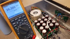
Passive Bridge Rectifier
Unloaded Supply Voltage: 26.4 V
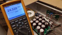
Loaded Supply Voltage: 24.5 V
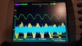
Loaded Supply Ripple: Approximately 15mV pp
I will try and do the active bridge now. If not now, then tomorrow.
Later I will look at power supply hamonics etc.
Unloaded Supply Voltage: 26.4 V
Loaded Supply Voltage: 24.5 V
Loaded Supply Ripple: Approximately 15mV pp
I will try and do the active bridge now. If not now, then tomorrow.
Later I will look at power supply hamonics etc.
Attachments
Last edited:
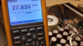
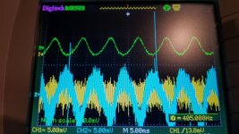
LT4320 Active Bridge Rectifier
Unloaded Supply Voltage: 27.6
Loaded Supply Voltage: 26.1
Loaded Supply Ripple: Approximately 15mV pp
Power supply rpple is about the same but the shape is a little different.
Unloaded Supply Voltage: 27.6
Loaded Supply Voltage: 26.1
Loaded Supply Ripple: Approximately 15mV pp
Power supply rpple is about the same but the shape is a little different.
Attachments

In both cases there is about 0.2 V lost across the resistors in the crc supply, when the supply is loaded by the amp.
So Loaded Passive vs Loaded Active is:
24.6V vs 26.1V
Just so you know my transformer has 19V secondaries.
24.6V vs 26.1V
Just so you know my transformer has 19V secondaries.
The increased loaded voltage by itself may be enough to justify the active bridge rectifiers. Sometimes being able to supply a higher Vds to the output Mosfets can translate into improved sonics. So, as Zen Mod asks, is there also a difference that you can hear?
BTW, which switching Mosfets did you use for the active rectifiers?
BTW, which switching Mosfets did you use for the active rectifiers?
- Home
- Amplifiers
- Pass Labs
- On A Hippie Trail, Head Full Of Zombie