I have Exicon MOSFETS for a build - ECX10N20 and ECX10P20's. One thing I was pondering is the disparity between the parts in terms of Ciss. Looking at the curves for Vgs vs Id and having both run at 1.0 Amp, the Ciss for the P-channel part is almost double the N-channel part (around 1100 pF).
[I think this has been discussed before for other MOSFETs, but I can't find it.]
The Spice models for the parts have Ciss about the same, which seems incorrect. So it would seem to make sense to adjust the gate stop resistor values so that the HF roll-off is about equal for both devices.
Comments?
[I think this has been discussed before for other MOSFETs, but I can't find it.]
The Spice models for the parts have Ciss about the same, which seems incorrect. So it would seem to make sense to adjust the gate stop resistor values so that the HF roll-off is about equal for both devices.
Comments?
The Hafler amplifiers which used the early Hitachi versions of these lateral Mosfets did, in fact, use different gate stopper resistors for the N and P-channel devices. The N-channel parts got 470Ω gate stoppers, and the P-channel parts got 220Ω.
Yes - that is what I was thinking - doubling up on the N-channel stoppers vs. P-channel. It would be interesting to adjust the Spice model for the P-channel value an see the effect on distortion. Having said that, the effects of the mismatch are probably minimal below 20KHz. The time constants are pretty small. I would guess this would show up on a square wave test with asymmetric rise/fall times.
Something else that was done was adding a small (20 pF to 47 pF) cap from gate to drain of the N-channel devices. This helped squelch any oscillation that might have occurred. The Hafler schematics show a larger value placed from gate to source, but most who modified the old amps preferred the smaller gate to drain capacitance.
Imitation F7 breadboard
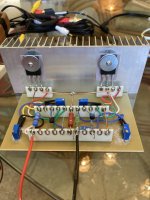
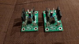
I posted this over in the F7 review thread. I am calling this an imitation (not a clone - "IF7"?) since I have no real first-hand knowledge of the schematic, but it seems to work nicely so far. Bias and offset adjustments easy to do with 15-turn pots. Did a quick listening test with trash speakers and it sounds good. I will probably do a PCB and get a real amp chassis soon, then do some real measurements and listening tests.
Old-timers will appreciate the Tektronix-style ceramic/silver terminal strips.
Attachments
I have Exicon MOSFETS for a build - ECX10N20 and ECX10P20's. One thing I was pondering is the disparity between the parts in terms of Ciss. Looking at the curves for Vgs vs Id and having both run at 1.0 Amp, the Ciss for the P-channel part is almost double the N-channel part (around 1100 pF).
[I think this has been discussed before for other MOSFETs, but I can't find it.]
The Spice models for the parts have Ciss about the same, which seems incorrect. So it would seem to make sense to adjust the gate stop resistor values so that the HF roll-off is about equal for both devices.
Comments?
If you want, although not completely necessary.
Oops - I goofed. Obviously the third is NOT that far down! But still not bad.
I should add that I am using the LTspice built-in models for LSK170B/LSJ74B for the fets and the Ian Hegglun/keantoken lateral models found here for 10P20/10N20 Exicon parts. And here is the LTspice log for the previously mentioned FFT.
View attachment 841276
Check Idss on those ltspice models, on one of them there is an error.
Don't remember off the top of my head which one is modeled erroneously.
Check Idss on those ltspice models, on one of them there is an error.
Don't remember off the top of my head which one is modeled erroneously.
Did you mean the FETs or the Laterals?
Did you mean the FETs or the Laterals?
One of the LSK jfet spice models has an error, I don't recall off the top of my head which one. Check Idss to be sure the models you have are ok.
Testing an F4 beast variation. 10kHz square wave.
If you have a very small amount of overshoot with your F4, then placing 1000pF across R24, and R25 completely cleans it up to perfection.
Don't do more than 1000pF though. You could possibly try 500pF (I haven't tried it ).
I tried 200pF but it wasn't enough, and 22nF didn't work anywhere near as well.
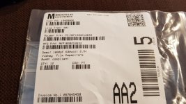
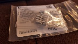
The radial caps I used are a real bastard to install so I purchased these 1000pF axial polypropylene film capacitors.
Attachments
Active rectification is on my list of things to try too, pico. Let us know how they perform....
(I'm inching along on JamJar. I bought enclosures from China and it looks like they used beach sand to grind the backs of them -- it's taking quite some time and elbow grease to get the mounting locations dead-flat. They're not a patch on the cases I got from Thailand....)
(I'm inching along on JamJar. I bought enclosures from China and it looks like they used beach sand to grind the backs of them -- it's taking quite some time and elbow grease to get the mounting locations dead-flat. They're not a patch on the cases I got from Thailand....)
4315F Aluminum Power Amplifier Chassis Class A amplifier Enclosure HiFi DIY Case | eBay
(On the plus side it's one of the few I could find with 70mm heatsinks instead of 40mm. It's bigger than it looks.)
(On the plus side it's one of the few I could find with 70mm heatsinks instead of 40mm. It's bigger than it looks.)
- Status
- This old topic is closed. If you want to reopen this topic, contact a moderator using the "Report Post" button.
- Home
- Amplifiers
- Pass Labs
- On A Hippie Trail, Head Full Of Zombie