Test build of the power supply board revealed a (minor and easily fixable) error in the least important part of the whole circuit - the fast turn-off. Details and a workaround are below. I am sorry about this.
The fast turn-off disengages the protection relay quickly when AC power disappears. In is not necessary - Omicron switches on and off silently. Yet, I added it for purely aesthetic reasons - just as I wanted the power-on LEDs turn off quickly instead of fading over few seconds, I wanted the relay to turn off immediately when the power is off.
The fast turn-off circuit is super simple:

The power supply board carries a separate small rectifier (D3) that charges a capacitor (C14). When the AC power disappears, C14 discharges faster than the bulk capacitors in the power rails, the gate of Q53 goes less negative compared to its source, and it causes the relay to disconnect the load (see also post #53 for the explanation of how this works).
Except that there is nothing to discharge C14! In the first version of the power supply board (see post #35), it was the power-on LED that discharged the capacitor. I received some comments that this creates an unwanted dependency - should there be no LED connected, there would be no fast turn off. So I added a separate rectified for the LED - but forgot to add a discharge circuit for C14. My bad. The circuit was not needed in the first place, so I paid least attention to it and made a mistake.
There are a few options to deal with the problem:
1. Do nothing. Omicron switches off silently, so there is no practical need in fast turn off. You can build the power supply board as is, or you can omit the whole fast-turn off circuit altogether. The relay will disengage a few seconds after the power is removed, that's all.
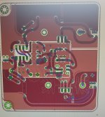
2. Solder a 1kOhm to 4.7kOhm (not critical) resistor on the bottom of the power supply board that will discharge C14:

Here, the resistor is 2.2kOhm. This makes the whole thing work as expected.
3. Wait for an amended power supply board.
Again, I am sorry about this.
The fast turn-off disengages the protection relay quickly when AC power disappears. In is not necessary - Omicron switches on and off silently. Yet, I added it for purely aesthetic reasons - just as I wanted the power-on LEDs turn off quickly instead of fading over few seconds, I wanted the relay to turn off immediately when the power is off.
The fast turn-off circuit is super simple:
The power supply board carries a separate small rectifier (D3) that charges a capacitor (C14). When the AC power disappears, C14 discharges faster than the bulk capacitors in the power rails, the gate of Q53 goes less negative compared to its source, and it causes the relay to disconnect the load (see also post #53 for the explanation of how this works).
Except that there is nothing to discharge C14! In the first version of the power supply board (see post #35), it was the power-on LED that discharged the capacitor. I received some comments that this creates an unwanted dependency - should there be no LED connected, there would be no fast turn off. So I added a separate rectified for the LED - but forgot to add a discharge circuit for C14. My bad. The circuit was not needed in the first place, so I paid least attention to it and made a mistake.
There are a few options to deal with the problem:
1. Do nothing. Omicron switches off silently, so there is no practical need in fast turn off. You can build the power supply board as is, or you can omit the whole fast-turn off circuit altogether. The relay will disengage a few seconds after the power is removed, that's all.
2. Solder a 1kOhm to 4.7kOhm (not critical) resistor on the bottom of the power supply board that will discharge C14:
Here, the resistor is 2.2kOhm. This makes the whole thing work as expected.
3. Wait for an amended power supply board.
Again, I am sorry about this.

I had missed the message with BOM for the SMT, maybe you can still edit the first post to include it there?
Is the R7 and R27 value change suggested in #203 for everyone or just for those using the power supply mentioned above? Thanx
Is the R7 and R27 value change suggested in #203 for everyone or just for those using the power supply mentioned above? Thanx
Greetings all,
I will be building the SMT version, and I have a recollection that the entire BOM can be uploaded to Digikey or Mouser instead of entering part by part manually.
Could someone advise me how to do it, or has anyone already created such a list?
Kindest regards,
M
I will be building the SMT version, and I have a recollection that the entire BOM can be uploaded to Digikey or Mouser instead of entering part by part manually.
Could someone advise me how to do it, or has anyone already created such a list?
Kindest regards,
M
Here is the link to the Mouser project. The link was also included in #172.
Note Mouser does not currently have the relays (G6K-2P-Y DC24) n stock, expecting them in the end of May. Digi-Key and others have plenty.
Note Mouser does not currently have the relays (G6K-2P-Y DC24) n stock, expecting them in the end of May. Digi-Key and others have plenty.
The BOM for the PSU has Mouser part MKP2F021501B00KSSD for C2, C3, C8, C9 and the BOM and circuit lists this as 150nf. But Mouser have MKP2F021501B00KSSD being 15nf. Which is correct or am I confused?
Is this actually a problem or am I just confused?
Is this actually a problem or am I just confused?
I ran into the same hiccup, because alexcp mentions snubbers and the quasimodo jig, which is generally 150nf, I went ahead and ordered MKS2D031501C00KSSD from mouser.
If anyone is curious, R3/R4 came out to be 91ohms on the Talema 70054K transformers on my quasimodo jig. I tested 3 transformers, each winding pair on the transformer came out to between 91-92ohm.
If anyone is curious, R3/R4 came out to be 91ohms on the Talema 70054K transformers on my quasimodo jig. I tested 3 transformers, each winding pair on the transformer came out to between 91-92ohm.
Looks like this part number is wrong on my BOM - I am sorry about that.
Here is the list of 0.15nF caps available at Mouser.
In case you don't have suitable caps, you can substitute more common 100nF caps (Mark Johnson recommends these to be 10x-20x value of C4 C5, see his article). Also, the power supply will work without these caps mounted, so you can run it until you get them.
My spares box reveals a bag of 7 MKP Wima 0.1uf 63v so I'll go with those for the moment. The Trafo is a Block FL18/18 I had on hand.In case you don't have suitable caps, you can substitute more common 100nF
No worries about the part number, there's an awful lot of moving parts to get together for a project like this...
G6K-2P-Y DC24 is the relay for the SMT board only (it is small):

G5V-2-H1-DC24 should work fine in the through-hole board:

It is a drop-in substitute for Fijitsu RY24W-K that I used (same coil resistance).
G5V-2-H1-DC24 should work fine in the through-hole board:
It is a drop-in substitute for Fijitsu RY24W-K that I used (same coil resistance).
Indeed. It was available when I was posting the BOM for the through hole board. Thankfully, the footprint of RY24W-K is quite common, so substitutes are available from e.g. Omron, KEMET or TE/AXICOM. Just remember to adjust R58 if the coil resistance is different from 2880 ohm.
Last edited:
Alex i just had an idea- how about applying this double nested feedback concept to a power amp? How would you go about doing it and what are the challenges? Please enlighten us.
I will post details in this thread that I just started.would you like to make your balanced line receiver public?
So the idea i voiced ealier, combining whammy output and omicron, i went and built it and it doesnt work. 1v output offset, crazy oscillation.
The layout was a crude first attempt. The opamp is meant to go on the underside of the board so the pinout is reversed.
When i bypass the 2nd opamp and turn the circuit into a regular whammy it works, so its either layout, comp values or else. The circuit connection seem error free tho.
Also im attaching a crude pasting of my schematic.
Any help will be appreciated. Thanks.
Attachments
Last edited by a moderator:
- Home
- Amplifiers
- Headphone Systems
- Omicron, a compact headphone amp with -140dB distortion