Ah, that should be fine, thanx.
Can we use the board as a preamp between your WM8816 Volume Controller and a stereo Neurochrome Modulus86 amp?
thank you
Are both HP and preamp outputs working at the same time, or one invalidates the other somehow?a line output to use Omicron as an ultra-low distortion preamp
Can we use the board as a preamp between your WM8816 Volume Controller and a stereo Neurochrome Modulus86 amp?
thank you
HP and line outputs are paralleled, but each has its own output filter - LRCR for HP, RCR T-filter for line. They can work at the same time, no problem. And yes, you can have both the headamp and speaker amp in one box with one volume control.
That's great! I actually will have a preamp box (input source selector > volume controller > Omicron) and the power amp box (2x modulus-86). Adding +1 to the GB.
Hello !
I'm very interested in this project as I want to make a nice & clean monitoring headphone amp for my home office where I can listen back the work I did in my studio (and pleasure listening also) and I have a few questions (keep in mind I'm low in electronic knowledge) :
- I already have a DIY passive monitoring that I don't use anymore with a stereo / mono / mono rev switch (it basically swaps the hot and cold of the balanced signals to do the proper additions / subtractions) and a 4 deck balanced stepped attenuator. So I plan to come into it balanced from my soundcard, which outputs 16 dBU. If a balanced line receiver is used after that, does the AMP gain needs to be reduced ? Coming balanced into the unbalancing stage also allows me to correct the inverting nature of the amp (and line output I suppose ? )
- I'm thinking of designing an active crossfeed circuit (the one I use in DSP needs copying & subtracting signals, a second order highshelf cut and a second order allpass filter, and it seems I can't do that easily in passive, but that will be a question for another thread). It will require 6 to 8 op-amps (probably NE5532) on top of the balanced line receiver. Considering I want to drive Focal Clears, which are 60 ohms (342 at their resonance) & 104 dB for 1 mW, will the power supply be able to drive the active electronics in parallel also or should I add a second one ?
Thanks in advance ! 🙂
Thinking of it, I actually have a new board that has not been published yet but may be useful to you - it's a high quality balanced line receiver (a lower distortion alternative to THAT1200 series) with optional ground sense output. You can add one to Omicron to make its input balanced, so that you can connect both Omicron and Modulus to the volume controller in parallel. I will PM you about that in the next day or two.I actually will have a preamp box (input source selector > volume controller > Omicron) and the power amp box (2x modulus-86).
Reducing Omicron's gain would require changes to its frequency compensation. Since its gain is not particularly high (x2.5), I'd recommend adjusting the gain of the balanced line receiver instead. It seems you could benefit from the same balanced line receiver board I mentioned above in this post, so I will PM you, too. And yes, in balanced connection, it is easy to swap the cold and hot wires to turn inverting into non-inverting. The phases of HP and line output in the SMT version of Omicron are the same (inverting).I plan to come into it balanced from my soundcard, which outputs 16 dBU. If a balanced line receiver is used after that, does the AMP gain needs to be reduced ? Coming balanced into the unbalancing stage also allows me to correct the inverting nature of the amp (and line output I suppose ? )
BTW can you hear the difference between inverting and non-inverting? On Stereophile's Test CD, the track #8 (Chanson hébraïque) has the polarity inverted somewhere in the middle, and you're invited to find that exact moment. Check it out!
I would not expect any problems with a single power supply. One NE5532 normally draw about 10mA, so eight of them will draw an additional 80 mA on each rail. The power supply board accommodates transformers up to 25/30VA (depending on construction), which is sufficient for up to 600mA rails. Those trafos won't fit into 1U enclosure, but 50mm and taller will be enough.It will require 6 to 8 op-amps (probably NE5532) on top of the balanced line receiver. Considering I want to drive Focal Clears, which are 60 ohms (342 at their resonance) & 104 dB for 1 mW, will the power supply be able to drive the active electronics in parallel also or should I add a second one ?
Since only a few people want SMD boards pre-populated, those few will get fully assembled and tested boards at the same price.update after price information

Awesome ! Thanks for you answer, I was indeed researching balanced line receivers circuits and was discovering that the subject is not as trivial as it would seem from far away.
For polarity, it really depends on the source. What makes it obvious : fast, low frequency notes. Especially electronic ones where bass notes are 100% the same each time. Sorry it's on another forum but the files are stream-able in a browser. Don't mind 2 of them with allpass. It's an 8 bar loop of a client's psytrance track (if that's your cup of tea) I worked on :
https://gearspace.com/board/so-much...monic-polarity-reversal-etc.html#post16183955
If you prefer downloading WAVs, they are on the preceding post. It's a bit more "obvious" in a well treated room than it is on headphones, but it's quite hearable. On the contrary, on my DIY 5 litres 3.5" Fullrange desktop speakers placed in an asymmetrical untreated room, it's very subtle, you have to know "where" and "what" to listen for. 🙂
Anyway, to not stay of topic too long, I look forward for your PM !
For the power supply, as I envision something with a big knob (like JDS Labs EL-AMP) and a few switches readily accessible, on my desk (maybe integrated in the furniture), I can totally put the power supply in another box under the desk.
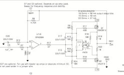
Besides using mostly SMT components, Omicron's SMT board:

adds a couple of extras to the schematic:. First, the crossfeed is switchable at runtime by a relay (K2):

Shorting the XFEED_SW connector connects the crossfeed.
Second, there is a line output with a separate RCR T-filter:

The output filter for headphones is based on the original idea by Nazar Shtybel and was discussed above.
The board is about 88×58mm with two layers and serves as the heatsink:

As mentioned above, the smallest SMT packages are 1206 for passive components and SOT-23 for diodes and transistors, so the board is quite solderable by hand.
adds a couple of extras to the schematic:. First, the crossfeed is switchable at runtime by a relay (K2):
Shorting the XFEED_SW connector connects the crossfeed.
Second, there is a line output with a separate RCR T-filter:
The output filter for headphones is based on the original idea by Nazar Shtybel and was discussed above.
The board is about 88×58mm with two layers and serves as the heatsink:
As mentioned above, the smallest SMT packages are 1206 for passive components and SOT-23 for diodes and transistors, so the board is quite solderable by hand.
@alexcp - First, a huge thank you providing this project. I admire your approach in making it accessible to builders of varying experience. The documentation and support are exceptional. I also appreciate the extensive discussion re: the design intentions along with the Q&A in the thread. I've read the thread a few times.
My plan is to build 4 versions. I'll learn a lot, have some fun, and have new amps for day-in-day-out use.
Two TH builds will be separated by purpose. One will be for 50ohm and under HPs that subjectively and objectively need a bit more power to reach my desired listening levels (HE-6, LCD-X and the like). The other will be for 300ohm HPs. I will likely build both with the recommended crossfeed sections unaltered. The one for the HE-6 etc, I will run at a higher bias current with the recommended parts and heatsinking necessary. The 300 ohm version will be 'stock'.
The two SMD versions will also be separated by purpose. One may be battery powered at a later date. One will be for IEMs. If the battery powered version sees the light of day, it may be for IEMs also, but run at reduced rails and bias current.
Onto a few questions for you and any others that may offer suggestions/answers.
Patrick
Edited for formatting, and b/c imported 'smilies' aren't up yet with the site upgrade.
My plan is to build 4 versions. I'll learn a lot, have some fun, and have new amps for day-in-day-out use.
Two TH builds will be separated by purpose. One will be for 50ohm and under HPs that subjectively and objectively need a bit more power to reach my desired listening levels (HE-6, LCD-X and the like). The other will be for 300ohm HPs. I will likely build both with the recommended crossfeed sections unaltered. The one for the HE-6 etc, I will run at a higher bias current with the recommended parts and heatsinking necessary. The 300 ohm version will be 'stock'.
The two SMD versions will also be separated by purpose. One may be battery powered at a later date. One will be for IEMs. If the battery powered version sees the light of day, it may be for IEMs also, but run at reduced rails and bias current.
Onto a few questions for you and any others that may offer suggestions/answers.
- I didn't notice in the thread any mention of why the relay selectable cross-feed was not included in the through-hole version. I'm certainly not questioning it's exclusion, and I could build one with and one without, but is there any insight you could offer? Note - I fully realize that it was part of the design intent, but it's on the SMT version.
- I will need volume pots for all the builds. You also mention that the input impedance (post #67) could be raised depending on the source, and that seems to be a recommendation at this point, correct? If I use a 10k linear pot as described in post #2, I would assume, but I am not sure, that I would not need to 'alter' the components from the 'original' schematic correct? The pot would now be the overriding component in determining input impedance? Would going to a 20k (or higher) value have any meaningful negative effect? I ask b/c at least one of the amplifiers would be for high-sensitivity IEMs, and (I think) the higher maximum impedance may be a benefit at lower listening levels, particularly with a linear profile and trying to get past the general channel mis-match found with some pots at high attenuation. However, I could be completely off-base. Admittedly some of this flies right past me.
- Based on posts #67 and #2, along with the schematics I have a few questions.
- For SMD (BoM not yet released, but schematic posted). R17, R18, and C3 in post #67 correspond to C37, C38, and C23 in the posted build schematics accordingly, and the values match. (12k, 12k, and 33n). If adding a 10k pot, would you recommend using the 'original' values of 3k9, 4k3, and 100n?
- For Through-hole (BoM and schematic posted). The equivalent parts identifiers on the schematics are the same as noted above. However, in the full schematic, C37, C38, and C23 are 3k9, 4k3, and 100n accordingly. However, the BoM posted has the 'updated' values. I got the schematic from post #42 linked from post #1, and the BoM from post #155. Would you recommend the 'updated' 12k, 12k, 33n configuration in addition to the pot or leaving it as 3k9, 4k3, 100n?
- For SMD (BoM not yet released, but schematic posted). R17, R18, and C3 in post #67 correspond to C37, C38, and C23 in the posted build schematics accordingly, and the values match. (12k, 12k, and 33n). If adding a 10k pot, would you recommend using the 'original' values of 3k9, 4k3, and 100n?
- Probably everyone's least favorite question; do you have a recommended pot? I have never purchased a linear vs. log taper/audio taper pot. I've searched fairly extensively from the parts suppliers I frequent (Mouser, Digi-key, Arrow, Parts Connexion, and Markertek. I admit to getting overwhelmed. As an example, here is a link to Mouser with Potentiometers, 2-gang, 1 turn, Horizontal, 10k, Linear, No Switch as the search criteria. Any help to get started and/or other key criteria to narrow the search would be greatly appreciated. Something with an Alps RK27 footprint / pin pattern would be ideal, but I know that is a lot to ask. I can wire accordingly and/or make a small PCB for other types. I can't solder wire to pins very well, and I find my soldering reliability pretty poor even when I'm successful. So, lugs are an option.
https://www.mouser.com/c/passive-components/potentiometers-trimmers-rheostats/potentiometers/?number of gangs=2 Gang&number of turns=1 Turn&orientation=Horizontal&resistance=10 kOhms&switch type=No Switch&taper=Linear&instock=y
- Based on posts #67 and #2, along with the schematics I have a few questions.
Patrick
Edited for formatting, and b/c imported 'smilies' aren't up yet with the site upgrade.
Last edited:
1. The story with switchable crossfeed: the SMT board has it because it also has a line output - presumably you wouldn't want crossfeed for anything except headphones. The through-hole board has no line output, so the crossfeed is permanent (or permanently absent, that's the builder's choice). The fun of switching crossfeed on and off while listening to Pink Floyd 😉 was unintended and discovered accidentally. My own SMT board with headphones connected has crossfeed permanently on.
2. With an inverting amplifier like Omicron, a volume control with good angle-to-gain law is a linear pot with resistance between 5 and 10 times the input impedance of the amplifier. For example, 10k or 20k pot for the original version with 2k input impedance and 20k to 50k pot for the 6k input impedance option. Withn these values, the law closely resembles an ideal log characteristic: (blue is Omicron 6k + 50k pot, gray is an ideal log pot, orange is a typical "audio" taper pot):

An additional benefit of using a linear (vs. audio taper) pot is that they often have better matching between gangs.
So yes, if your source is able to drive a 1-2kOm without distortion, go ahead and use a 10k linear pot with other values as per post #2 schematic - this configuration runs in my build. A pot with a higher resistance (e.g. 20k) will give you a slower volume increase at low volume.
If you use the higher impedance option from the BOM, you'd be, in principle, better off with a linear 25k or 50k pot - but 10k also seems to work ok, so this isn't so critical.
By the way, the names of the same parts in the TH and SMT verisions are identical. On both boards, R17 R18 C3 corresponds to R37 R38 C23 in the other channel.
3. I don't really have a recommended pot. I use Bourns or Vishay Sfernice conductive plastic or cermet resistors, and they work fine despite very light (i.e. too easy to rotate) shaft. Apls RK09 and RK27 worked great for me in the past, as did DACT and Goldpoint stepped attenuators (note RK27, DACT and Goldpoint only come with audio taper). Also, here on the forum EUVL published a brief review of various volume controls and a cool and very XEN-like mod to Alps RK27 series.
Nothing stops you from trying out a couple of options and perhaps upgrading the volume control later.
2. With an inverting amplifier like Omicron, a volume control with good angle-to-gain law is a linear pot with resistance between 5 and 10 times the input impedance of the amplifier. For example, 10k or 20k pot for the original version with 2k input impedance and 20k to 50k pot for the 6k input impedance option. Withn these values, the law closely resembles an ideal log characteristic: (blue is Omicron 6k + 50k pot, gray is an ideal log pot, orange is a typical "audio" taper pot):
An additional benefit of using a linear (vs. audio taper) pot is that they often have better matching between gangs.
So yes, if your source is able to drive a 1-2kOm without distortion, go ahead and use a 10k linear pot with other values as per post #2 schematic - this configuration runs in my build. A pot with a higher resistance (e.g. 20k) will give you a slower volume increase at low volume.
If you use the higher impedance option from the BOM, you'd be, in principle, better off with a linear 25k or 50k pot - but 10k also seems to work ok, so this isn't so critical.
By the way, the names of the same parts in the TH and SMT verisions are identical. On both boards, R17 R18 C3 corresponds to R37 R38 C23 in the other channel.
3. I don't really have a recommended pot. I use Bourns or Vishay Sfernice conductive plastic or cermet resistors, and they work fine despite very light (i.e. too easy to rotate) shaft. Apls RK09 and RK27 worked great for me in the past, as did DACT and Goldpoint stepped attenuators (note RK27, DACT and Goldpoint only come with audio taper). Also, here on the forum EUVL published a brief review of various volume controls and a cool and very XEN-like mod to Alps RK27 series.
Nothing stops you from trying out a couple of options and perhaps upgrading the volume control later.
Basically, it is the balanced input and the ground sensing output sections from my volume control boards without the volume control in between.would you like to make your balanced line receiver public? I´m interested too...
Thank you so much! The completeness of your answers is second-to-none.
I also greatly appreciate the links to Patrick's (EUVL) work. That was fun reading.
I'm still scratching my head re: a few things, but that's why I like new projects. Always something to learn.
With thanks!
Patrick
I also greatly appreciate the links to Patrick's (EUVL) work. That was fun reading.
I'm still scratching my head re: a few things, but that's why I like new projects. Always something to learn.
With thanks!
Patrick
Part list for the SMT version:
As for the through hole version, part numbers are just examples with one exception: the Murata pulse transformer. Here is the link to the project on Mouser. Note that Mouser doesn't have the relays in stock at the moment, but Digi-Key and many others do have them in large quantities.
All the comments to the through hole BOM apply. Also, be careful with replacing BAV99, as a change in forward voltage drop would affect the quiescent current of the output stage.
| Qty | Value | Device | Package | Parts | Example P/N | TH/SMT |
|---|---|---|---|---|---|---|
| 1 | 78602/3MC | Pulse transformer | Murata 786 series | L1 | 78602/3MC-R | SMT |
| 2 | RS1D | Diode | SMA | D1, D51 | RS1D_R1_00001 | SMT |
| 8 | BAV99 | Dual diode | SOT23-3 | D2, D3, D4, D5, D6, D7, D9, D11 | BAV99,235 | SMT |
| 1 | BC856 | PNP BJT | SOT23-3 | Q52 | BC856B,215 | SMT |
| 2 | 2N7002 | N-Ch MOSFET | SOT23-3 | Q51, Q53 | T2N7002AK,LM | SMT |
| 2 | 33n | Polypropylene film capacitor | Radial LS=5mm | C3, C23 | MKP2C023301B00KSSD | TH |
| 4 | 1000u | Aluminum electrolytic capacitor | Radial D=10..13mm | C13, C14, C33, C34 | EEU-FC1E102E | TH |
| 8 | 47u | Aluminum electrolytic capacitor | Radial D=5mm | C11, C12, C31, C32, C9, C10, C29, C30 | EEU-FC1E470B | TH |
| 4 | 10n | Ceramic capacitor NP0 (C0G) | 1206 | C6, C26, C45, C46 | C1206C103J5GACAUTO | SMT |
| 4 | 15p | Ceramic capacitor NP0 (C0G) | 1206 | C7, C8, C27, C28 | C1206C150J5GACTU | SMT |
| 2 | 1n5 | Ceramic capacitor NP0 (C0G) | 1206 | C5, C25 | 12065A152JAT2A | SMT |
| 7 | 1u | Ceramic capacitor X7R | 1206 | C41, C42, C43, C44, C51, C52, C53 | CL31B105KBHNFNE | SMT |
| 6 | 330p | Ceramic capacitor NP0 (C0G) | 1206 | C1, C21, C4, C15, C16, C24 | C1206C331J5GAC | SMT |
| 2 | 5p6 | Ceramic capacitor NP0 (C0G) | 1206 | C2, C22 | CC1206DRNPO9BN5R6 | SMT |
| 2 | G6K-2P-Y | Relay | G6K-2P-Y | K1, K2 | G6K-2P-Y-DC24 | TH |
| 1 | 2-way | Header | 0.1 inch pitch | XFEED_SW | 22-23-2021 | TH |
| 3 | 3-way | Header | 22-11-2032 | HEADPHONES, INPUT, LINE_OUT | 22-23-2031 | TH |
| 1 | 5-way | Header | 22-11-2052 | POWER | 22-23-2051 | TH |
| 1 | GREEN | LED | 1206 | LED | 156120VS75000 | SMT |
| 1 | LM339D | Quad comparator | SOIC-4 | U51 | LM339DR | SMT |
| 2 | PZT2222A | NPN BJT | SOT223 | Q1, Q21 | PZT2222A,135 | SMT |
| 2 | PZTA2907A | PNP BJT | SOT223 | Q2, Q22 | PZT2907A,135 | SMT |
| 2 | NE5532 | Dual opamp | SOIC8 | U1, U21 | NE5532DR | SMT |
| 4 | 68 | Thin film resistor | 1206 | R13, R14, R33, R34 | RT1206FRE0768RL | SMT |
| 8 | 100 | Thin film resistor | 1206 | R20, R40, R41, R42, R45, R46, R53, R54 | RT1206FRE07100RL | SMT |
| 2 | 100k | Thin film resistor | 1206 | R56, R60 | RT1206FRD07100KL | SMT |
| 4 | 10k | Thin film resistor | 1206 | R11, R12, R31, R32 | RT1206FRD0710KL | SMT |
| 4 | 12k | Thin film resistor | 1206 | R17, R18, R37, R38 | RT1206FRE0712KL | SMT |
| 4 | 15k | Thin film resistor | 1206 | R5, R6, R25, R26 | RT1206FRE0715KL | SMT |
| 1 | 1Meg | Thin film resistor | 1206 | R55 | RT1206FRE071ML | SMT |
| 3 | 1k | Thin film resistor | 1206 | R10, R30, R59 | RT1206FRE071KL | SMT |
| 4 | 1k3 | Thin film resistor | 1206 | R1, R2, R21, R22 | RG3216P-1301-D-T5 | SMT |
| 4 | 2.2 | Thin film resistor | 1206 | R15, R16, R35, R36 | RC1206FR-072R2L | SMT |
| 2 | 20k | Thin film resistor | 1206 | R51, R52 | RT1206FRE0720KL | SMT |
| 2 | 24k | Thin film resistor | 1206 | R19, R39 | RT1206FRE0724KL | SMT |
| 2 | 2K2 | Thin film resistor | 1206 | R43, R58 | RT1206FRE072K2L | SMT |
| 2 | 300 | Thin film resistor | 1206 | R8, R28 | RT1206FRE07300RL | SMT |
| 1 | 33k | Thin film resistor | 1206 | R57 | RT1206FRE0733KL | SMT |
| 2 | 470k | Thin film resistor | 1206 | R9, R29 | RT1206FRE07470KL | SMT |
| 6 | 4k7 | Thin film resistor | 1206 | R3, R4, R7, R23, R24, R27 | RT1206FRE074K7L | SMT |
| 4 | 51k | Thin film resistor | 1206 | R47, R48, R49, R50 | RT1206FRE0751KL | SMT |
As for the through hole version, part numbers are just examples with one exception: the Murata pulse transformer. Here is the link to the project on Mouser. Note that Mouser doesn't have the relays in stock at the moment, but Digi-Key and many others do have them in large quantities.
All the comments to the through hole BOM apply. Also, be careful with replacing BAV99, as a change in forward voltage drop would affect the quiescent current of the output stage.
One of my Omicrons finally got its own chassis:


Modushop Galaxy 1U 230x230mm was used because I had it. I placed the volume control pot in the back, close to the input connectors and the amplifier's input, and extended its shaft. Otherwise, the build is pretty straightforward.
Modushop Galaxy 1U 230x230mm was used because I had it. I placed the volume control pot in the back, close to the input connectors and the amplifier's input, and extended its shaft. Otherwise, the build is pretty straightforward.
Omicron's power supply:

is built on a two layer 128x78mm PCB with four mounting holes in the corners of a 120x70mm rectangle:

The board carries a PCB-mounted power transformer, two regulators (LM317/LM337 based), a power loss detector that works with Omicron's protection circuit, and an optional separate small rectifier for a power-on indication:

The power supply includes an LRC filter on the transformer's primary side and CRC snubbers on the secondary (see Mark Johnson's excellent topic on snubbers and his Quasimodo jig for details). The rest of the circuit is straightforward.
The board is designed to accommodate low-profile PCB mounted transformers such as Talema's 7005xK (15VA) 7006xK (25VA) toroids - they share the same footprint but have different heights - or, preferably, BLOCK FL series (10 to 30VA versions also share the same footprint but differ in height). Talema 15VA and BLOCK FL 10VA and 14VA (and maybe 18VA) transformers will fit into a 1U enclosure.
There are similar transformers from other manufacturers (HAHN, Myrra, etc.) that may fit the board, but their pinouts may be different and must be verified first.
Since all the recommended transformers have dual primary windings (115V+115V), the board includes a simple primary voltage selector (115VAC/230VAC).
When selecting a transformer for this board, keep in mind that some voltage will drop on the LRC filter in the primary circuit - the more the better, as long as the regulators do not drop out of regulation. A practical approach is to select R1 and R2 on the schematic above so that under full load current, the DC voltage at the input of each regulator is 3V higher than the output voltage (e.g. 20V for 17V rails). The resistors' value will depend on your primary voltage, too.
is built on a two layer 128x78mm PCB with four mounting holes in the corners of a 120x70mm rectangle:
The board carries a PCB-mounted power transformer, two regulators (LM317/LM337 based), a power loss detector that works with Omicron's protection circuit, and an optional separate small rectifier for a power-on indication:
The power supply includes an LRC filter on the transformer's primary side and CRC snubbers on the secondary (see Mark Johnson's excellent topic on snubbers and his Quasimodo jig for details). The rest of the circuit is straightforward.
The board is designed to accommodate low-profile PCB mounted transformers such as Talema's 7005xK (15VA) 7006xK (25VA) toroids - they share the same footprint but have different heights - or, preferably, BLOCK FL series (10 to 30VA versions also share the same footprint but differ in height). Talema 15VA and BLOCK FL 10VA and 14VA (and maybe 18VA) transformers will fit into a 1U enclosure.
There are similar transformers from other manufacturers (HAHN, Myrra, etc.) that may fit the board, but their pinouts may be different and must be verified first.
Since all the recommended transformers have dual primary windings (115V+115V), the board includes a simple primary voltage selector (115VAC/230VAC).
When selecting a transformer for this board, keep in mind that some voltage will drop on the LRC filter in the primary circuit - the more the better, as long as the regulators do not drop out of regulation. A practical approach is to select R1 and R2 on the schematic above so that under full load current, the DC voltage at the input of each regulator is 3V higher than the output voltage (e.g. 20V for 17V rails). The resistors' value will depend on your primary voltage, too.
Human perception of loudness is a function of not so much sound pressure but of the distortion level - that is, to be loud, the sound must be distorted. For that reason, a single pure tone is unsuitable as an emergency signal, so ambulances use multiple tones or sweeps. By the same token, when listening to recorded music, many people adjust volume up until they hear just enough distortion.
With Omicron, the experience is quite different. You add volume, but the distortion's not there. You add more, and more, until you realize that the sound pressure is much higher than your normal listening level - but the loudness is not there, just pure music.
With Omicron, the experience is quite different. You add volume, but the distortion's not there. You add more, and more, until you realize that the sound pressure is much higher than your normal listening level - but the loudness is not there, just pure music.
^ My transducers add enough distortion to make me want to stop at comfortable levels on most days. I have a few HP amps with distortion low enough as to be claimed non-audible. I don't think I listen to them at higher SPLs than HP amps with very audible THD (either solid state made to sound "tubey" or tube amps). However, other than measuring the voltage output (which I've done), I can't really provide much more context. I'm not intending to contradict, but provide a variation on the theme.
HPs make much more of a difference (to me). I find some HPs unlistenable regardless of the amplifier or SPL ... some I quite like. EQ can make some of the unlistenable... pleasant. In some cases, but rarely, an amplifier with more distortion can make some HPs sound a bit more pleasant. As an example, I rather like the Sennheiser HD 800 with a few tube amps, but I find that headphone to be less than pleasant with a low distortion chain. I'd say that's the exception rather than the rule from my own limited experiences, but... we're all in this for fun.
I've started to create my own parts list from the schematic, board layout, and information above. However, I've got a few things to confirm. Are you also going to release a parts list for the PSU? If it has already been posted, and I've missed it, apologies.
Once again, thank you!
Last edited:
This is perhaps a stupid question, but I have absolutely 0 electronic design understanding despite my best efforts, so I thought to just straight up ask.
Would there be any issues with connecting a small active cooling fan directly to the power supply output rails? (Of course, the fan voltage spec would be suitable) Or would something like that screw with the distortion of the amplifier? It's likely, because the rotating magnetic assembly will probably induce some eddy currents into the system. But I'm not sure, I am just an amateur.
I am also aware something like this is somewhat excessive but I thought why not, if I will build myself an Omicron why not use the best parts I can get my hands on to create a really polished end result.
Thanks!
parts list for the PSU
| Qty | Value | Device | Package | Parts | Example P/N |
|---|---|---|---|---|---|
| 2 | 10uF 50V | Aluminum electrolytic capacitor | Radial D=5mm | C14, CLED | EEUFC1H100L |
| 4 | 22u 50V | Aluminum electrolytic capacitor | Radial D=6.3mm | C10, C11, C12, C13 | EEUFC1H220 |
| 2 | 4700u 25V | Aluminum electrolytic capacitor | Snap-in D=25mm | C6, C7 | B41231B7478M000 |
| 4 | 150nF | Ceramic or MKS/MKT film capacitor | Radial LS=5mm | C2, C3, C8, C9 | MKP2F021501B00KSSD |
| 2 | 10nF | Ceramic or MKS/MKT film capacitor | Radial LS=5mm | C4, C5 | MKS2G021001A00MSSD |
| 1 | 10mH | Common mode choke | LS=7x8 or 10x13mm | L1 | SU9VD |
| 1 | 2-way | Connector | 0.1in contact spacing | LED | 22-23-2021 |
| 1 | 2-way | Connector | 0.312in or 0.4in contact spacing | AC_MAINS | See text |
| 1 | 5-way | Connector | 0.1in contact spacing | OUT2 | 22-23-2051 |
| 6 | 1N4148 | Diode | DO35 | D1, D2, D3, D4, D5, D6 | 1N4148-T26A |
| 2 | DB104 | Diode bridge | DIP4 | BR1, BR2 | DB104 |
| 2 | 1in tall | Heatsink | Aavid 531x02 | 531002B02500G | |
| 1 | LM317T | LM317T | TO220 | LM317 | LM317T |
| 1 | LM337T | LM337T | TO220 | LM337 | LM337T |
| 1 | 2x18V | Power transformer | BLOCK FL 10VA, Talema 15VA | TR1 | See post #174 |
| 2 | TBD | Resistor 0.25W | D=2.5mm L=6.3mm | R3, R4 | See text |
| 1 | 1k | Resistor 0.25W | D=2.5mm L=6.3mm | R9 | MFR-25FBF52-1K |
| 1 | 1k8 | Resistor 0.25W | D=2.5mm L=6.3mm | RLED | MFR-25FBF52-1K8 |
| 2 | 22 | Resistor 1W | D=2.8mm L=9.0mm | R1, R2 | ROX1SJ22R |
| 2 | 160 | Resistor metal film 0.25W | D=2.5mm L=6.3mm | R5, R7 | MFR-25FBF52-160R |
| 2 | 2k | Resistor metal film 0.25W | D=2.5mm L=6.3mm | R6, R8 | MFR-25FBF52-2K |
| 1 | 47n | X2 safety capacitor | Radial LS=15mm | C1 | 890324025009CS |
| 4 | n/a | TO220 thermal pad | n/a | LM317, LM337 | 43-77-9G |
| 2 | n/a | M3x8 round head screw | n/a | LM317, LM337 | n/a |
| 2 | n/a | M3 nut | n/a | LM317, LM337 | n/a |
| 4 | n/a | M3 washer | n/a | LM317, LM337 | n/a |
| 2 | n/a | M3 spring washer | n/a | LM317, LM337 | n/a |
- The height of the assembled power supply board depends on the height of the transformer (see post #174), two heatsinks, and two large electrolytic capacitors (C6 C7). It makes sense to choose all these parts with approximately the same height, e.g. 1 inch / 25mm. Note that C6 and C7 have max allowable diameter 25mm.
- The common mode choke (L1) can be just about any of the many similar parts with inductance between 2 and 22mH. The PCB accepts chokes with pins in 10x13mm or 7x8mm rectangle.
- The AC input connector can be either a Molex KK396 or KK508 3-way header with middle pin removed, or a three-way 0.2 in pitch terminal block without its middle contact. Of course, soldering bare wire to the PCB is also possible.
- Only one output connector (the 5-way OUT2) is needed for Omicron.
- As noted above, the value of R1 R2 can be adjusted between 10 and 100 ohm should the voltage drop on the regulators under full load is too small or too big.
- The value of the snubber resistors R3 R4 should be chosen based on the transformer used, e.g. with the help of Mark Johnson's Quasimodo test jig. To give you an example, I found the optimal value was 39 ohm for AMVECO 70064K toroidal transformer and 470 ohm for BLOCK FL10/18 UI type.
- Resistors R5 R6 R7 R8 set the output voltage for the regulators, The value shown in the table set 17V rails. Should you want lower voltage, you need to choose these resistors accordingly. Some popular values would be R5=R7=150 ohm, R6=R8=1.3 kOhm for 12V and R5=R7=200 ohm, R6=R8=2.2 kOhm for 15V,
- Thermal pads are optional as the heatsinks are not connected to anything on the board.
Those fans can inject lots of noise into the power rails. In my view, it makes little sense to filter out external noise and then add noise from the fan.connecting a small active cooling fan directly to the power supply output rails
Never tested that, but I'd expect degradation only in terms of max voltage swing at the output - which is the max voltage swing at the opamp output less the Vgs of the output transistor and less the voltage drop on the 10ohm source resistors. Any difference in linearity will most likely be swamped by the loop gain of Omicron.
I take this opportunity to remind that the group buy will close tonight.
I take this opportunity to remind that the group buy will close tonight.
- Home
- Amplifiers
- Headphone Systems
- Omicron, a compact headphone amp with -140dB distortion