I've notice that this design uses the venerable NE5532 op amp, which was class leading in its day. It doesn't have rail to rail outputs though, which will limit the swing of the output stage. You may want to consider OPA1655 or OPA2156 as an optional upgrade, since these have rail to rail output and higher bandwidth. The higher bandwidth may even allow you to modify the closed loop bandwidth of the system for an even faster response. The OPA is quite cheap too.

Its an aside, but - Lem was a brilliant writer, and I must now re-visit.Stanisław Lem said in His Master's Voice: "Information at second hand always gives an impression of tidiness, in contrast with the data at the scientist’s disposal, full of gaps and uncertainties."
Kudos for the quote!
This has been successfully resolved - the problem was in a broken trace on the PCB. One more Omicron is live!I've reflowed almost of all components of the malfunctioning channel ... but nothing changed.
I finally made this THT amp.
Special thank to @alexcp !
He really helped me solve many problems.
It made a little hum ... so I connected ground of headphone adapter to earth ground then hum gone.
I connected my Audeze LCD 2C to this amp.
This is a very powerful and easy listening headphone amp.
Special thank to @alexcp !
He really helped me solve many problems.
It made a little hum ... so I connected ground of headphone adapter to earth ground then hum gone.
I connected my Audeze LCD 2C to this amp.
This is a very powerful and easy listening headphone amp.
Attachments
Hi Alex,
Would there be any point in having separate ground returns to the power supply ground for the four electrolytic caps (2×100uF and 2x1000uF) and the input and feedback resistors just to keep the last ground return cleaner? I know the currents are relatively small but it is to my knowledge practice in power amps. It could in theory be potentially beneficial but would it make a difference in your design? Also thanks you for your blogs on feedback and others. Makes for intersting reading.
Would there be any point in having separate ground returns to the power supply ground for the four electrolytic caps (2×100uF and 2x1000uF) and the input and feedback resistors just to keep the last ground return cleaner? I know the currents are relatively small but it is to my knowledge practice in power amps. It could in theory be potentially beneficial but would it make a difference in your design? Also thanks you for your blogs on feedback and others. Makes for intersting reading.
Can you please elaborate?could in theory be potentially beneficial
I had a look your power supply and noticed how you wired up the amp pcb. Creative not seen before. That explains your commemts earlier on in the forum that how groundwiring is done on the pcb is critical for ultimate performance. That makes my question irrelevant and I ll retract it.
Thank you 🙂
For the benefit of others who may be reading this: feedback must be taken from the same points where the load is connected. This idea is mainstream for the "hot" (= actively driven) point. The same requirement applies to the "cold" end. However, in the context of a single-ended connection, where the "cold" end is grounded, the concept of "the same point" becomes confusing, as two ends of a ground wire or PCB trace may or may not be "the same point". The terms "clean ground" and "dirty ground" mean "pretty much the same point" and "not quite the same point", respectively. Should you take the feedback network to the power supply, you would need to take the load there, too - and vice versa. On our boards, this issue has been taken care of, so no extra wiring is required.
For the benefit of others who may be reading this: feedback must be taken from the same points where the load is connected. This idea is mainstream for the "hot" (= actively driven) point. The same requirement applies to the "cold" end. However, in the context of a single-ended connection, where the "cold" end is grounded, the concept of "the same point" becomes confusing, as two ends of a ground wire or PCB trace may or may not be "the same point". The terms "clean ground" and "dirty ground" mean "pretty much the same point" and "not quite the same point", respectively. Should you take the feedback network to the power supply, you would need to take the load there, too - and vice versa. On our boards, this issue has been taken care of, so no extra wiring is required.
Last edited:
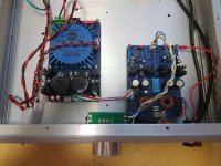
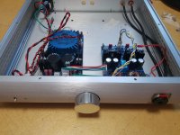
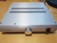
Here, I completed mine! 🙂
https://quebecdiy.forumactif.com/t99-amplificateur-d-ecouteurs-omicron
Seems to sound really good but I have to spend some time with it with a couple headphones, but so far I'm really satisfied with it. It's still missing all the labels but I will put them shortly. 🙂
The transformer and the new wiring for the volume pot is not on the pictures unfortunately...
Thanks
Do
Hi Alex,
Could you please advise - does it make any sense to use Toshiba 2SC47932SA/2SA1837 for this build?
Any potential advantages/disadvantages?
It just happens that I still have a bunch of those (original Toshiba).
Apologies if this has been previously discussed already.
Many thanks in advance.
Victor
Could you please advise - does it make any sense to use Toshiba 2SC47932SA/2SA1837 for this build?
Any potential advantages/disadvantages?
It just happens that I still have a bunch of those (original Toshiba).
Apologies if this has been previously discussed already.
Many thanks in advance.
Victor
These are packaged in TO-220 and have a different pinout (BCE), which won’t fit the PCB (designed for TO-126 with the ECB pinout). Also, these transistors are quite a bit slower than BD139/140. We have not tested them, and although I wouldn't expect any problems, you’d need to make sure the amplifier is stable with them.
Hi Alex
I read an article and the author prefferred to put the common mode choke after the rectifier bridge. In your design that would mean two. I guess it might assist against diofe switching noise as well. Any opinion?
I read an article and the author prefferred to put the common mode choke after the rectifier bridge. In your design that would mean two. I guess it might assist against diofe switching noise as well. Any opinion?
We have not tried secondary-side common-mode chokes, yet. To me, that would mean two chokes, one for each rail, and since they'd be on the secondary side with higher currents, they'd be larger and/or have less inductance. Perhaps you can try it out? Keep in mind that a suitable choke must have a sufficient leakage inductance to suppress both common-mode and differential-mode noise on the frequencies where the regulator's loop gain fizzles out.
After the third Omicron group buy closed in June last year, there has been a number of requests for more boards, so I'd like to see if there is interest for another group buy. If interested, please sign up here.
The last GB for the Omicron boards closes tomorrow. There won't be another GB for the Omicron boards anytime soon. If you're thinking about building this headlamp but sitting on the fence, now is the time to sign up.
- Home
- Amplifiers
- Headphone Systems
- Omicron, a compact headphone amp with -140dB distortion