Thank you Zen for the info!
I mean - writing in bold and big font , pretty much the same as shouting
of FW format amps , I can think of bridged F4 ( which means two regular stereo ones driven with balanced signal) , F5 Turbo (iteration you're ready for) , damn big BA3 ...... maybe you could even like amp from recent alive thread - AB 100W amp
there is slight possibility that Babelfish M25's 50W/4R could make some difference , counting on fact that 40W of these is in A class , but I can't guarantee that
so ..... build and try

I've nearly finished this amp (only front and lid remaining). It sounds great! 😛
Thank you Papa for making it available (and Tea-Bag for making the job easy for me providing the PCBs and Edcors).
Just for fun, below is the distortion when providing 5V into 8 Ohms. Only left channel shown but the two channels are remarkably alike.
It will not be my last DIY power amp 😀.
Thank you Papa for making it available (and Tea-Bag for making the job easy for me providing the PCBs and Edcors).
Just for fun, below is the distortion when providing 5V into 8 Ohms. Only left channel shown but the two channels are remarkably alike.
It will not be my last DIY power amp 😀.
Attachments
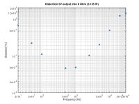
I used an HP8903B audio analyzer: File:HP8903B audio analyzer.jpg - Wikipedia
Clipping 1% distortion at 1kHz into 8Ohm is at 2.95V input level for my amp, Nelson states 3V, so close enough in that respect.
The slightly above 1% distortion at 20kHz and >3 watts shouldn't alarm anyone. If you dissipate that power level at 20kHz in any speaker I can think of, at least I have left the room.
With the M2 clone, I hear details of my recordings i didn't hear before, served in a very pleasant way.
Sorry for my english. I used google translate.
I am trying to start clone M2 one channel separately first. Power supply is on JeffYoungs decoupled stereo pcb. Connection of the power supply itself and everything ok . It's approx. +/- 23 VDC on the output. After connecting m2 by light bulb on the primary winding the transformer it turns on for a second, goes out and then after a long moment begins to light up slowly and no longer goes off. I checked the voltage through resistor R13 and R14. It rises from 0 to 0.48V exactly at the same time as the light bulb shines and the supply voltage drops. Something is wrong but I don't know what should I check. All resistors are checked.
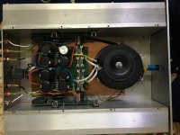
That's my wiringView attachment 778763
I am trying to start clone M2 one channel separately first. Power supply is on JeffYoungs decoupled stereo pcb. Connection of the power supply itself and everything ok . It's approx. +/- 23 VDC on the output. After connecting m2 by light bulb on the primary winding the transformer it turns on for a second, goes out and then after a long moment begins to light up slowly and no longer goes off. I checked the voltage through resistor R13 and R14. It rises from 0 to 0.48V exactly at the same time as the light bulb shines and the supply voltage drops. Something is wrong but I don't know what should I check. All resistors are checked.
That's my wiringView attachment 778763
Bulb tester is "only" for initial testing , mostly PSU etc.
you can't use it with whole amp , which is drawing 60W or so , Bulb tester is doing work as current limiter
place your voltmeters as prescribed ( output offset , Iq ( across one source resistor) and power amp without Bulb tester
you can't use it with whole amp , which is drawing 60W or so , Bulb tester is doing work as current limiter
place your voltmeters as prescribed ( output offset , Iq ( across one source resistor) and power amp without Bulb tester
I read that if the bulb tester lights up, it's not good. I don't want to smoke anything. Especially jfets.
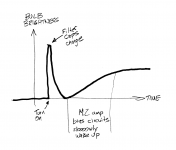
it turns on for a second, goes out and then after a long moment begins to light up slowly and no longer goes off.
PSU charging from empty is the first light, once PSU is charged the light dims.
Then the amplifier begins to turn on and the bias current becoming normal, light glows again.
If it lights up with no load on the PSU, then it's not good. If you've got the amp running then you have a load and the bulb is going to light up at least a little.
(One of the Zen variations makes use of this and uses bulbs as constant-current-sources.)
(One of the Zen variations makes use of this and uses bulbs as constant-current-sources.)
Unfortunately. I turn on and there is a short flash of light bulb then nothing for a while. Then slowly brightens and at the same time the supply voltage drops and increases voltage through R13 / R14. It stabilizes to around 0.48V but the bulb stays on.
My M2x draws 125 watts from the AC mains. That's the "equilibrium" value after turn-on and warmup, 5 minutes after flipping the power switch. I measured that number using a cheap "Kill A Watt" meter I bought from Amazon for $21.
That's enough current to light the bulb of my dim-bulb tester. So, in equilibrium, the dim bulb tester is not dark. It is lit.
_
That's enough current to light the bulb of my dim-bulb tester. So, in equilibrium, the dim bulb tester is not dark. It is lit.
_
Attachments

Hi darrr,
the behaviour you describe is exactly what we expect from an M2, as Mark, Jeff and 6L6 already wrote. I would go ahead with Zen Mod's suggestion of starting the amp channel without light bulb tester, but with the multimeters connected as Zen Mod described.
Regards, Claas
the behaviour you describe is exactly what we expect from an M2, as Mark, Jeff and 6L6 already wrote. I would go ahead with Zen Mod's suggestion of starting the amp channel without light bulb tester, but with the multimeters connected as Zen Mod described.
Regards, Claas

This is my first such a big diy project and thank you all very much for help. The good news is that both channels seem to work well. Bad , that I unfortunately damaged 1pcs sj74 and maybe sk170. It hurts.... I measured the values according to those in the attached drawing point(I don't have high quality DMM):
A = 78.5 / 78.7 mV
B = -75.5 / -69.5 mV
C = 3.4 / 4mV
Voltages through R13 / 14 are 0.610V offset was successfully set to 0
Voltages on opto legs:
1-2 = 1V
4-5 = 9.5V
Voltages on rail +/- 22V .
It takes 50 seconds from turning on until the current begins to flow by R14 / R13. Is there anything else I should check? If not, I can already collect money for chassis from modushop [emoji846]
Last edited:
- Home
- Amplifiers
- Pass Labs
- Official M2 schematic