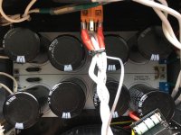
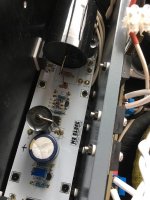
I would post a few pictures of the completed amp from a few different angles.
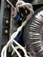
Make doubly sure that the foil around the toroid can't possibly create a conductive path around/through the toroid (maybe by touching the mounting bolt). Otherwise you'll invoke Faraday's law in a rather exciting way, probably melting the foil.
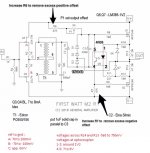
Once you've double (and triple) checked all the wiring, check the voltage across R13 and R14, being extremely careful not to touch anything else with your multimeter probes. Ideally you should get some of those little clip on probes. While you're at it, measure the voltage across R3 and R4, as well as the DC offset voltage across the speaker terminals when the inputs are shorted.
R13 and R14 should be somewhere around 650mV
R3 and R4 should be somewhere around 100mV
And you should be able to get the offset voltage very close to zero by playing with the trimmer pot (P1)
Do this for both left and right.
I assume some of this is redundant information, but if you post those numbers and some updated pics, the talented folks here can probably isolate your problem quite quickly.
Make doubly sure that the foil around the toroid can't possibly create a conductive path around/through the toroid (maybe by touching the mounting bolt). Otherwise you'll invoke Faraday's law in a rather exciting way, probably melting the foil.
Once you've double (and triple) checked all the wiring, check the voltage across R13 and R14, being extremely careful not to touch anything else with your multimeter probes. Ideally you should get some of those little clip on probes. While you're at it, measure the voltage across R3 and R4, as well as the DC offset voltage across the speaker terminals when the inputs are shorted.
R13 and R14 should be somewhere around 650mV
R3 and R4 should be somewhere around 100mV
And you should be able to get the offset voltage very close to zero by playing with the trimmer pot (P1)
Do this for both left and right.
I assume some of this is redundant information, but if you post those numbers and some updated pics, the talented folks here can probably isolate your problem quite quickly.
case is simply too small to have M2 satisfactory hum-free
Al foil around Donut is not just non-effective, it's also dangerous
so , bigger case, where you can manage greater physical distance between Donut and signal xformers, then troubleshooting problematic channel
Al foil around Donut is not just non-effective, it's also dangerous
so , bigger case, where you can manage greater physical distance between Donut and signal xformers, then troubleshooting problematic channel
Thank you for all the suggestions.
update:
Here are some photos. I took away the foil wrap.
I measure at PSU outputs with my little oscilloscope and found ripples. There should be no ripples as I tested with my other amps, they are virtually a straight line.
I will take apart and check the filtering part of PSU.
yes, I will get a bigger and deeper Alu case.
- - - - - - - - - - - - - - - - - - - - - - - - - - - - - - - - - - - - - -
Here is the info & measurements:
Trafo: 18Vac x2 secondary / 400VA (local voltage: 220V/50Hz)
Teabag PSU pcb: output after Filtering: +20.96Vdc / -20.82Vdc (only PSU : +23.xV/-23.xV)
Teabag M2 pcb original version.
I re-soldered every single joint of the left channel PCB, both top and bottom.
- - - - - - - - - - - - - - - - - - - - - - - - - - - - - - - - - - - - - -
Left Channel: (problematic)
low hum - independant of volume control / only half the volume level of Right channel.
Hum: I compared it with youtube video clip of various low Hz, I can confirm it is 100Hz. Probably the post filtering ripple Hz?
Left channel is still 5C cooler than right channel.
R13 / R14: 608mV
A: 96mV
B: -80mV
C: 0.0mV ( trimpot adj. )(drifts between 0.00-0.3mV)
Voltage at optocoupler:
1-2: 1.03V
4-5: 9.76V
Output DC Offset drifts between -0 to -40mV.
- - - - - - - - - - - - - - - - - - - - - - - - - - - - - - - - - - - - - -
Right Channel: (normal / insignificant hum (higher pitch than left channel) / good sounding)
R13 / R14: 608mV
A: 90.8mV
B: -80mV
C: 0.0mV ( trimpot adj. ) (drifts between 0.00-0.5mV)
Voltage at optocoupler:
1-2: 1.03V
4-5: 9.54V
Output DC Offset drifts between +0 to +55mV.
- - - - - - - - - - - - - - - - - - - - - - - - - - - - - - - - - - - - - -
seems most of the measurements are within the optimal range.
- - - - - - - - - - - - - - - - - - - - - - - - - - - - - - - - - - - - - -
Now my question:
Will the DC offset at output be stable after some time? both channels' DC offsets fluctuate quite a lot after it is turned on. I keep turning it back to 0mV every 5 minutes.
Again thank you all for your help.
After I port to a bigger case and examine the PSU , I will post again.
Attachments
-
 73513c48-80d9-47c5-ad6e-b3da98460a77.jpg66.8 KB · Views: 505
 -
 7efd8f94-8d10-4f1c-845d-aaed44138030.jpg63.6 KB · Views: 477
 -
 71ffa5f5-b853-48de-859c-6f6d32d98996.jpg75 KB · Views: 477
 -
 ffdbe45c-e1f6-4f96-b009-c359c57ec7e4.jpg85.2 KB · Views: 496
 -
 Increase R6 to remove excess positive offset.jpeg264.5 KB · Views: 502
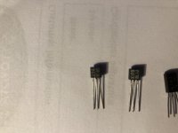
I would like to build the M2 amp but unfortunately I am in the situation of mismatched input fets (see pict) I have a shed-load of both and I am looking to trade (ideally) for some 2sk170V or maybe the other way around & make them both BL. I don't know enough about this amp to know what would work best. Maybe even mixing and matching V and BL grade is ok?
PM me if you want to discuss a trade.
PM me if you want to discuss a trade.
Attachments
Just an FYI ...
There's a set of M2 PCBs in the diyAudio Store; they are called "M2x". These implement the First Watt M2 amplifier schematic exactly.
However,
The M2x PCB design moves the input transistors (in fact the entire input stage circuitry) onto a removable "daughter card". The M2x provides five different circuit options (five different stereo pairs of input daughter cards), four of which do not use Toshiba JFETs. And of course the fifth one is the exactly-as-designed-by-Nelson-Pass circuit which DOES use Toshiba JFETs.
This might interest you because it offers up the possibility of building and listening to the M2 amplifier, before you actually locate and purchase the JFETs you are now seeking. Build one of the other four input daughter cards that doesn't use Toshibas. Finish the amp. Debug it. Burn it in. Listen to it. Enjoy it. You may like it so well that you re-think just how critical and urgent it might be, to get Toshiba parts. diyAudio members who have built and listened to an M2x of their own, seem to have several different favorites. Some like the exactly-as-designed-by-Nelson-Pass input daughter cards the most. With Toshiba JFETs. Others like the single ended (non push-pull) Class A input daughter card the most. Still others prefer the daughter card that uses a Diamond Buffer topology. And quite a few actually do love the card with the high tech Silicon-Germanium opamp circuit (!!wow!! in a Nelson Pass amp!!) the most.
It might be worth taking a quick look to see what you think.
The diyAudio First Watt M2x
.
Last edited:
I see what you're saying and I thank you. I am looking to build the original circuit mostly because it's the simplest and I think I would have everything I need minus the silly mismatch issue with fets and the interstage trafo. 😀
If you measure the Idss of your transistors and can match them, it will be completely fine. The upper end of the V range and the lower end of the BL range overlap. (Around 6.0mA Idss) You may get lucky.
The V, BL, and G range are all the same transistors from the same process, same wafer and the same fab, The designator are just for the factory measured Idss groupings.
The V, BL, and G range are all the same transistors from the same process, same wafer and the same fab, The designator are just for the factory measured Idss groupings.
http://www.firstwatt.com/pdf/art_beast.pdf
This article is a great read, and it has the information you need.
This article is a great read, and it has the information you need.
Just for information.
Grade Y, not any longer available, around 2mA
Grade GR, around 3 to 6 mA
Grade BL, around 6 to 10/12 mA (I am not absolutely sure)
Grade V over 10 mA
Grade Y, not any longer available, around 2mA
Grade GR, around 3 to 6 mA
Grade BL, around 6 to 10/12 mA (I am not absolutely sure)
Grade V over 10 mA
Revisiting my M2 Clone
I'm in the process of dismantling my MoFo breadboard amp to mount it in a proper chassis, sooo I've been listening to my M2 Clone again. I built with Grimberg's boards using Toshiba 2SK1530/2SJ201 MOSFETs and LS JFETs, store PS boards and homemade mono chassis.


I never did up my bias for the Toshibas and was curious what difference it would make. I got ARTA going so I could measure THD before and after. Then added 1.3 ohm resistors in parallel with 0.47 ohm source resistors and a 1 ohm resistor in parallel with 221 ohm, R11.
Sound card is Digital Audio Labs, CardDeluxe. Here's a baseline of sound card loopback.

1.3A bias, 1W into 8 ohm dummy

1.55A bias, 1W into 8ohm dummy.

It lowered some of the higher ordered harmonics!
I still wasn't satisfied, more reading in the thread and I realized.... maybe my Edcor autoformers got magnetized? I bought 10 each of the store's LSK170/LSJ74 and matched as best I could. Not a perfect match though. I added offset pot later because I worried about DC on input Edcor xfmr. Too late they were already magnitized.
Demagnitazation to the rescue! I followed the recomendations from Bill Whitlock at Jensen white papers and lowered those higher harmonics further.

M2 still great on female vocals, even better now. I'm listeing to Norah Jones, Day Breaks album as I write this....sweeeet!
Now all that is left is to maybe shield input xfmr to lower that 120 Hz buzz. My ear has to be 4 inches from the speaker to hear.... maybe some other day.
Cinco
I'm in the process of dismantling my MoFo breadboard amp to mount it in a proper chassis, sooo I've been listening to my M2 Clone again. I built with Grimberg's boards using Toshiba 2SK1530/2SJ201 MOSFETs and LS JFETs, store PS boards and homemade mono chassis.
I never did up my bias for the Toshibas and was curious what difference it would make. I got ARTA going so I could measure THD before and after. Then added 1.3 ohm resistors in parallel with 0.47 ohm source resistors and a 1 ohm resistor in parallel with 221 ohm, R11.
Sound card is Digital Audio Labs, CardDeluxe. Here's a baseline of sound card loopback.
1.3A bias, 1W into 8 ohm dummy
1.55A bias, 1W into 8ohm dummy.
It lowered some of the higher ordered harmonics!
I still wasn't satisfied, more reading in the thread and I realized.... maybe my Edcor autoformers got magnetized? I bought 10 each of the store's LSK170/LSJ74 and matched as best I could. Not a perfect match though. I added offset pot later because I worried about DC on input Edcor xfmr. Too late they were already magnitized.
Demagnitazation to the rescue! I followed the recomendations from Bill Whitlock at Jensen white papers and lowered those higher harmonics further.
M2 still great on female vocals, even better now. I'm listeing to Norah Jones, Day Breaks album as I write this....sweeeet!
Now all that is left is to maybe shield input xfmr to lower that 120 Hz buzz. My ear has to be 4 inches from the speaker to hear.... maybe some other day.
Cinco
I am a big fan of balanced operation and connections and maybe this is a really silly idea but...would it be possible to do a balanced input on the M2 with two unity gain stages for hot&cold then into a pair of EDCOR (or whatever) in a yet-to-be-determined connection and secondary impedance that would do the summation and voltage gain then continue forward into the output stage?
I think there is a pretty good chance that idea might be possible. But wait there's more. A number of clever circuit topologies could perhaps be discovered, which arrange the polarity/phase of the eight (!!) total transformer windings to give additional "marketing feature" functionality. Conceivably: extra gain; perfect cancellation of even order harmonics; independent drive of output pullup and output pulldown (maybe even with two copies of the optical bias control loop); might perhaps be some of the possibilities that you could decide to investigate.
If I look past your defensive sarcasm, I am afraid there is nothing to 'discover' here. Only very simple ideas to gently consider, some test to conduct and potentially some different transformers to source. All in keeping with the original NP idea of zero feedback. Something that I am no longer equipped or have time to do and I was curious if this idea had been proposed by smarter people here. Thanks.
Last edited:
some fun we had in Funny F6 thread....... and few things applicable here
what this country needs is - proper 6-fillar repeater coil
what this country needs is - proper 6-fillar repeater coil
I am a big fan of balanced operation and connections and maybe this is a really silly idea but...would it be possible to do a balanced input on the M2 with two unity gain stages for hot&cold then into a pair of EDCOR (or whatever) in a yet-to-be-determined connection and secondary impedance that would do the summation and voltage gain then continue forward into the output stage?
I am as well, and I was thinking about a solution using transformers. In the end I decided to build a balanced Aikido and use two output stages. It’s not the idea you were after but I guess that one is also possible, playing with two different transformers per channel...
- Home
- Amplifiers
- Pass Labs
- Official M2 schematic