shouldn't 2 1n4148 in series clamp the voltage to 1.2v in the same way to the LM385Z-1.2 ?
What is the advantage of LM385Z-1.2?
Sorry for stupid questions I need to learn
PS. Others on this forum ask even more basic things: how to wire a led to the PSU, so I think my questions are legitimate
What is the advantage of LM385Z-1.2?
Sorry for stupid questions I need to learn
PS. Others on this forum ask even more basic things: how to wire a led to the PSU, so I think my questions are legitimate
Try some experiments and see what happens. 90% of the cost of an M2 amplifier clone is in the heatsinks, chassis, power supply, I/O connectors, and power transformer. The amp channel boards & their electronic parts, are a tiny fraction of the overall cost. So if you destroy two or three amp channel boards while experimenting, the cost of replacement isn't prohibitive. And you won't need to rely upon the opinions of others.
I have all parts except these exotic LM385Z-1.2 and would like to avoid an order to mouser only for this piece
what is the characteristic of the LM385Z-1.2 that makes it mandatory? steep conduction curve compared to normal diode?
what is the characteristic of the LM385Z-1.2 that makes it mandatory? steep conduction curve compared to normal diode?
buy locally
Reichelt, Distrelec, Rutronic usw.
in this hobby, you need to buy more than one thing, for future
so, buy anything else, to feel lesser burden even of local shipping
Reichelt, Distrelec, Rutronic usw.
in this hobby, you need to buy more than one thing, for future
so, buy anything else, to feel lesser burden even of local shipping
Ye I know buy large quantities, stock and have fun experimenting during the winter.
Could-I use laterals with F4 style bias and no degeneration resistors?
Could-I use laterals with F4 style bias and no degeneration resistors?
I built my M2 with Laterals (2SJ201 / 2SK1530). Have used standard M2 bias method, with smaller degeneration resistors (0R22) and some adaptions in series resistor to optocoupler. I have about 1.8 A of bias current.
There is a discussion about this, including recommendations by Zen Mod on how to use Laterals with M2, somewhere further back in this thread.
Regards, Claas
There is a discussion about this, including recommendations by Zen Mod on how to use Laterals with M2, somewhere further back in this thread.
Regards, Claas
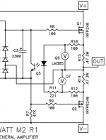
The M2 output stage bias current is set by (1) the Vfwd of the optoisolator; (2) the resistance and tolerance of R13 + R14
Unfortunately, R13 and R14 are usually 5% resistors, and the optoisolator Vfwd specified min and max are quite wide. So the M2 output stage bias current is not controlled to great precision.
Fortunately this is easy to overcome, simply by hand matching the parts before stuffing and soldering. 4N35 optoisolators cost USD 0.36 in quantity=10 and 0R47 3W resistors cost USD 0.21, so it is not prohibitively expensive to buy 5X too many parts. Then cherry pick the best matching set according to your own measurements. Done. The pride of craftsmanship, building an M2 with very precisely controlled bias current, can bring great satisfaction.
_
Attachments
The M2 output stage bias current is set by (1) the Vfwd of the optoisolator; (2) the resistance and tolerance of R13 + R14
Unfortunately, R13 and R14 are usually 5% resistors, and the optoisolator Vfwd specified min and max are quite wide. So the M2 output stage bias current is not controlled to great precision.
Fortunately this is easy to overcome, simply by hand matching the parts before stuffing and soldering. 4N35 optoisolators cost USD 0.36 in quantity=10 and 0R47 3W resistors cost USD 0.21, so it is not prohibitively expensive to buy 5X too many parts. Then cherry pick the best matching set according to your own measurements. Done. The pride of craftsmanship, building an M2 with very precisely controlled bias current, can bring great satisfaction.
_
isn't it possible to influence the bias current changing the value of R11?
Sure, go ahead and cherry pick R10, R11, and R12 too. But they're already 1% metal film resistors, so they contribute very little to the variation of output stage bias current. You'll have a lot more leverage when you precisely match Vfwd and R13 and R14.
I believe they are, since they have the same pinout as verticals - they are what I used, and I didn't have to do any awkward leg-crossings to get them to work.aren't 2SJ201 / 2SK1530 vertical mosfets?
With laterals, source resistors are not needed and the opto can be replaced with a 10k trimmer. Biggest difference would be lower damping factor.never tried M2 with laterals?
isn't it possible to influence the bias current changing the value of R11?
Yes, carefully!
- Home
- Amplifiers
- Pass Labs
- Official M2 schematic