With laterals, source resistors are not needed and the opto can be replaced with a 10k trimmer. Biggest difference would be lower damping factor.
any advantage in using TL431 ( à la F4) or a string of 1n4148 to bias the laterals?
but 0r47 source resistors decrease damping factor too?
lower Yfs of Laterals could be compensated by the absence of source resistors?
Last edited:
Is it possible to put a 500 pot insted of R11?Yes, carefully!
A trimpot is simpler, with R6 & R7 @ 47k, current ~ 0.5mA, too low for TL431.any advantage in using TL431 ( à la F4) or a string of 1n4148 to bias the laterals?
Yes, 2x0r47 effectively in parallel increase Zo by 0r235.but 0r47 source resistors decrease damping factor too?
Yfs ~1 compared to IRFP240 ~4, still higher Zo, closer to a tube amp territory.lower Yfs of Laterals could be compensated by the absence of source resistors?
Distortion profile
I read Nelson's article "Practical Mosfet Testing for Audio" and several posts about the Transconductance shelving associated with Vishay IRFP9240. So I thought to finish the project properly I finally got around to check the distortion distribution of my M2 clone.
It is indeed 2nd order dominant at high frequencies, which is expected with the Vishay parts I think? The amp has quite a bit more distortion >500Hz than the original though. It still sounds fine to me 🙂.
What is the current through the outputransistors with the original 221ohms resistor?Is it possible to put a 500 pot insted of R11?
aroundish
most important is that two channels are close to each other regarding Iq, which means all important parts are from same or close batch
that, counting on sorta broad range of characteristics of optocouplers
in short, anything between 1A3 and 1A5 is not surprising to me
most important is that two channels are close to each other regarding Iq, which means all important parts are from same or close batch
that, counting on sorta broad range of characteristics of optocouplers
in short, anything between 1A3 and 1A5 is not surprising to me
Maybe it´s better to use a variable resistor to make them the same current.which means all important parts are from same or close batch
naah
most likely you'll get them ditto in 5-10% and that's close enough, considering concept of circuit
do not over-engineer, when there is no need
most likely you'll get them ditto in 5-10% and that's close enough, considering concept of circuit
do not over-engineer, when there is no need
I did the first steps on my M2 path and although i have read a bunch of stuff here before ordering, i managed to end up with a 4U 300mm Deluxe case. That works fine with a stock M2, but as soon as i tried some 2SK1529 / 2SJ200 and lowered R13/R14 to 0.34 ohm the case started running a bit too hot for my taste. The amp still seems to run stable, but i wanted to lower R13 / R14 further to about 0.22 ohm like several other members did it with the big brothers 2SK1530 / 2SJ201.
I want to avoid to switch to a 4U / 400mm case. Thats why i am thinking about dropping the rail voltage a bit to lower the idle power dissipation. I want to remove the DIYaudio store CRC PSU and use monolithic bridge rectifiers together with a juma Mosfet cap multiplier, that should drop about 4V. (getting rid of the diyaudio PSU would free up a lot of space in my small 4U 300mm case and i could mount my new toroidy trafo on the baseplate of the amp)
With my existing 500VA toroid my rail voltages are about ~22.7 - ~22.9 (slowly fluctuating). So if i would drop (4V - 0,3V (old PSU)) = 3,7V i would end up with rail voltages of about 19V. There will also be an additional voltage drop in the PSU due to higher Id of ~1.8A i am aiming at for the output tranistors.
Whats bad in dropping the rail voltage a bit? Loosing voltage headroom in the output stage is not a big deal to me. Sadly i live in a house where i am not allowed to listen to music very loud.
My question: is my idea of dropping the voltage to 19V totally nuts? Or is it worth the try? Costs for this experiment are low (juma cap mx). But to upgrade my case to 4U 400mm heatsinks will cost about 200 Euro again...
My advice is to get the 4U/400 or even 5U/400 and use the 4U/300 for another project like the F6. Since you are in Germany the shipping would be almost nothing compared what I have to pay for shipping a case.
Thank you for your answer.. Funny thing is my girlfriend thought i was building an amp for our big PA System when the 4U 300mm arrived. She was very surprised (in a negative way) after i explained that this case was intended for a "little" 25 Watt amp for my home system... When i go 4U/5U 400mm it may be a bit too big for our small living room.
Last edited:
Another solution might be to support your 4U/300 case with a slow and silent fan underneath ... look for posts by Zen Mod with the keyword "babysitter".
Even a slow fan adds a lot of heat dissipation capability.
Best regards, Claas
Even a slow fan adds a lot of heat dissipation capability.
Best regards, Claas
Thank you for your valuable advice, Claas. I will search for babysitter. If i remember correctly you are using 2SK1530/2SJ201 in your M2 @ about 1,8 A idle current. What size of case are you using? Are your heatsinks very hot?
With ~23V rail voltage and a measured idle current of about 1,5 A my heatsinks are getting very hot, but i can press my hands on them for minutes before it starts to hurt.
edit: found the babysitter, looks interesting.. Babysitter for papas koan Thread
With ~23V rail voltage and a measured idle current of about 1,5 A my heatsinks are getting very hot, but i can press my hands on them for minutes before it starts to hurt.
edit: found the babysitter, looks interesting.. Babysitter for papas koan Thread
Last edited:
If you can hold your hands on the sinks for a long time; there is nothing to worry now:
https://www.diyaudio.com/forums/pass-labs/353343-f5-bias-thermal-issues-2.html#post6176821
For my M2 with 2SJ201 / 2SK1530 and 0R22 resistors, I am using a case I built around heat sinks that are comparable to the 4U/400. I have about 24V rails and 1.8A bias. The sinks get nicely warm, but I can hold my hands on the sink indefinitely ... 🙂
Regards, Claas
chimey hot, bloody hot or *'%!§ hot?
Hi Claas, thanks for pointing me to this thermal tool 🙂
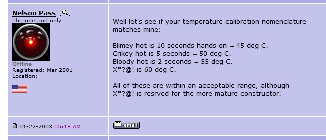
I can't believe that my heat sink is only 45°C hot according to this statement.. If i would guess they are >50°C at the top (= not the hottest spot on the heatsink). Maybe my hands are a less sensitive 😛 looks like i need a more objective tool for measuring temperatures..
ZM, what do you mean by "make a toy"?
A) build a "babysitter" fan base
B) lower rail voltages to 18V - 19V
C) get a 4U 400mm case and stuff everything inside?
regards, Addi
Hi Claas, thanks for pointing me to this thermal tool 🙂
I can't believe that my heat sink is only 45°C hot according to this statement.. If i would guess they are >50°C at the top (= not the hottest spot on the heatsink). Maybe my hands are a less sensitive 😛 looks like i need a more objective tool for measuring temperatures..
ZM, what do you mean by "make a toy"?
A) build a "babysitter" fan base
B) lower rail voltages to 18V - 19V
C) get a 4U 400mm case and stuff everything inside?
regards, Addi

- Home
- Amplifiers
- Pass Labs
- Official M2 schematic