I have been using a F5 with a 27V rails power supply. I would like to use this power supply for my M2 boards.
Is this possible? And if so, is there a way to lower the bias (r11 value?)?
All help will be greatly appreciated.
clarify need for lesser Iq
When using the 27VDC power supply the bias is 0.704V.
The heatsinks on my modushop 4U chassis are app. 50 degrees C after 60 minutes. The Mosfets (2SK1530+SJ201) are app. 80 degrees C.
And that is measured in a somewhat chilly listening room.
I wouldn't mind being able to reduce the bias a bit to lower the temperature..
The heatsinks on my modushop 4U chassis are app. 50 degrees C after 60 minutes. The Mosfets (2SK1530+SJ201) are app. 80 degrees C.
And that is measured in a somewhat chilly listening room.
I wouldn't mind being able to reduce the bias a bit to lower the temperature..
OK , referring to enclosed schm , try this :
decrease both R10 and R12 to 82R
decrease R11 to 100R
if that doesn't help enough , change source resistors (R13,R14) to 0R56 ..... knowing that that will increase Rout slightly
what is thermal interface you're using between mosfets and htsnk?
however , before all those , I would try upping case feet height (better air flow) and Babysitter too
Last edited:
Thanks, Zen Mod.
My thermal interface is Keratherm.
I will probably try your last suggestion.
My thermal interface is Keratherm.
I will probably try your last suggestion.
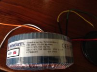
what did you order exactly and where?
As I'm in Australia I sourced a proper 240V unit from the local distributor
The distributor is called RF Waves
The owner has built an F5
Attachments
Last edited:
Well, I managed to kill my M2 build. The power supply tested good at 25v on each side. I mounted the amp boards to the heatsinks on the Dissipante 4U. Plugged it in with the test meter on DC volts hooked to the speaker connections on the right channel. The voltage read out climbed to over 19V and then pop both of the large resistors blew on the right channel, who knows what else died in the process.
I disconnected the power from the right channel and plugged the amp back in. But this time only momentarily touched the meter to the left speaker wires. It too climbed quickly and I removed the meter probes but no pop or smoke. The left heatsinks got warm as normal. I plugged a cheap speaker and music signal into that side and all I got is a good hum sound. I unplugged it before I did anymore expensive damage.
What would cause that high of DC voltage on the speaker outs. I don't see how the meter could have killed it which I guess would mean the left and right side have different issues then.
I used Thermaltak TG-7 on the mosfets along with these pads. I didn't think to check last night to make sure the TG-7 wasn't electronically conductive. Would shorting the mosfets to ground cause an issue like that?
Last edited:
Oooouch - sorry to hear that. The moral of the story - use a variac or a light bulb for the first power-up. It won't fix your problem but it could help you avoid damaging parts.
Oooouch - sorry to hear that. The moral of the story - use a variac or a light bulb for the first power-up. It won't fix your problem but it could help you avoid damaging parts.
I did the light bulb for firing up the power supply when I did that, I guess it might have signaled a problem this time but it blew that side pretty quickly. About the time I went "hey, the DC offset shouldn't be over 19V" it went pop!
A variac would have signaled that there was a problem with the DC Offset likely before something cooked but don't have one of those.
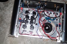
Nothing is visually cooked or looking like it is overheating in the other channel and it was powered up for a minute or so just no audio other than a light background hum through it. The mosfets in that channel seem to be warming to a normal level like there is power to them. And the sound out of the speaker sounds like an amp running at full volume with a wire picking up a hum and no signal attached.
Attachments
Last edited:
wiring , especially PSU rails to pcb ?
you didn't mix-up output mosfets ?
orientation of optocoupler ?
polarity of clamping diodes ?
resistor placement/value ?
mosfets well isolated from htsnk ?
plenty of things to check
you didn't mix-up output mosfets ?
orientation of optocoupler ?
polarity of clamping diodes ?
resistor placement/value ?
mosfets well isolated from htsnk ?
plenty of things to check
so ,what's your plan to check and what to change anyway ?
Unscrew the washers over the mosfets to make sure they are in the right place.
I checked the wiring from the PSU to the PCB last night but since I also double checked the orientation of the optocoupler before I installed it I'd say all the prior work is in question so I'll retrace the wiring.
I can see the diodes in some of my other pictures and they are correct.
Check the thermal paste and make sure it isn't conducting any current.
Double check the resistor values and placements.
If everything else checks out reverse the optocoupler and cross my fingers that the one channel works.
Then I have to figure out what all I killed on the other board and order replacements. Hopefully it is just the resistors and output mosfets
Pass DIY Addict
Joined 2000
Paid Member
Before you undo your mosfet bolts, check each pin with your DMM to make sure there is no connectivity from any of the three pins to the heatsink.
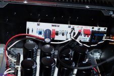
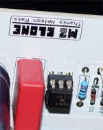
well, it looks like first mistake is the optocoupler is in wrong

shows the dot (next to the V) going towards the resistor not the capacitor
ta240,
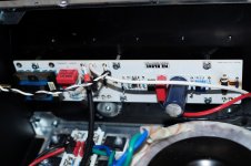
The top photo is the right hand channel but i think the thumbnail is showing the left hand channel.
Attachments
ta240,
The top photo is the right hand channel but i think the thumbnail is showing the left hand channel.
Dang, I need to quit working on this while I'm downing so much allergy medicine. This might be a good next winter project.

OK , referring to enclosed schm , try this :
decrease both R10 and R12 to 82R
decrease R11 to 100R
if that doesn't help enough , change source resistors (R13,R14) to 0R56 ..... knowing that that will increase Rout slightly
what is thermal interface you're using between mosfets and htsnk?
however , before all those , I would try upping case feet height (better air flow) and Babysitter too
I put the M2 in a 5U chassis, and now all problems are solved. I can run the 27V rail power supply with a bias of 704mV with no problems. My M2 sounds better than ever.
- Home
- Amplifiers
- Pass Labs
- Official M2 schematic