
Sorry for just disappearing, but I'v been busy and away for a while.
As you sugested Zen, minimal difference between cold and hot. And I have had no problems what so ever with zeroing the offset:
https://www.dropbox.com/s/5uworikuqlvj06n/Foto 2017-04-30 18 50 32.jpg?dl=0
https://www.dropbox.com/s/tucudkdqqe1qw8r/Foto 2017-04-30 18 51 23.jpg?dl=0
https://www.dropbox.com/s/xyevqtw7hu7yn2d/Foto 2017-04-30 18 52 01.jpg?dl=0
https://www.dropbox.com/s/hsufuwbezoy3xjk/Foto 2017-04-30 18 52 41.jpg?dl=0
Sound wise I'm very happy! 😀 It's som much clearer and more transparent than my old amp. There are a few more small bits and pieses that I have to finish, then I can start upgrading the rest, starting with DCG-3 and Pearl 2. And speakers, and phono, and NAS, and... 🙂
I'd like to thank You all for the help and support You've given me! Without Your help I would not had come to put this beautiful piece together. This is probably the most helpful forums I have ever attended!
I'd also like to say a special thank you to Mr. Pass, for making this possible for us all in the first place! I can't think of anyone else as generous with his/her knowledge and support. A role model to look up to!
put lid on , leave it cooking , recheck both offset and Iq after temp equilibrium
though m M2 is extremely civil there , minimal difference between cold and hot state
did you checked sound yet ?
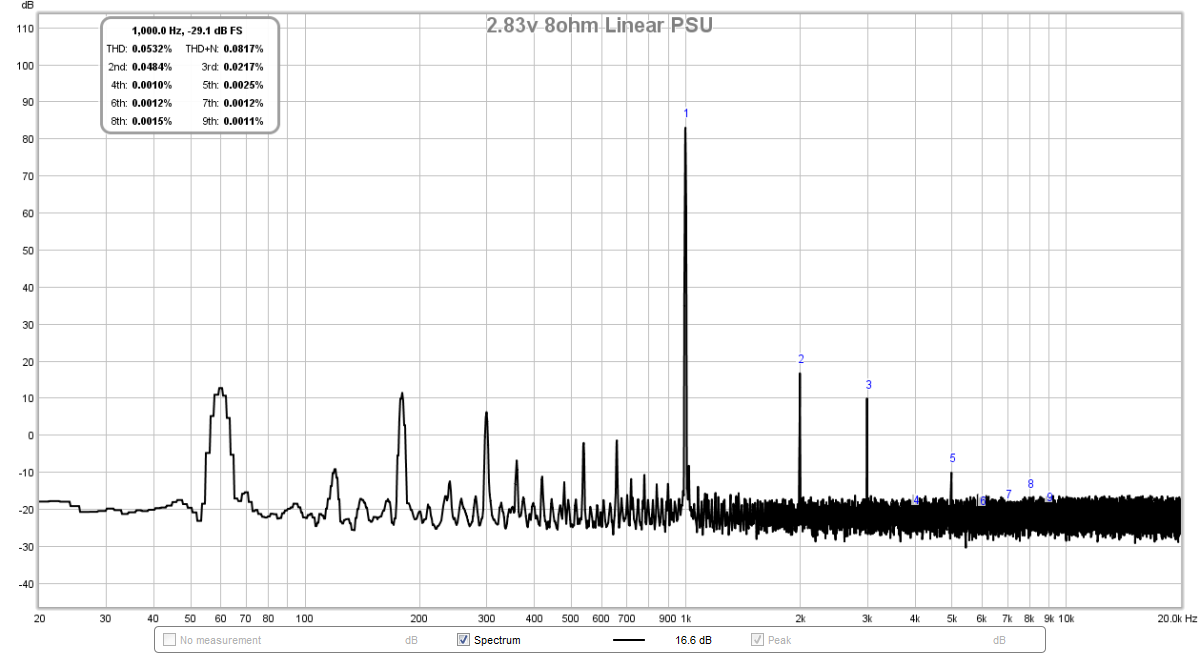
I have been working this issue of noise in my M2 for some time now in another thread. I am still getting audible hum when using a toroidal trafo PSU. After several variations on the PSU topology, my issue with hum remains. When I switch to a set of 5amp 24v smps supplies in series, there is no hum (and FFT confirms it). Even when inputs are shorted, the hum remains.
So has anyone else had problems with this and could it be the signal transformer picking up EMI from the transformer?
Here is what the FFT is currently showing (the stuff to the left of 1kHz remains even when inputs shorted):
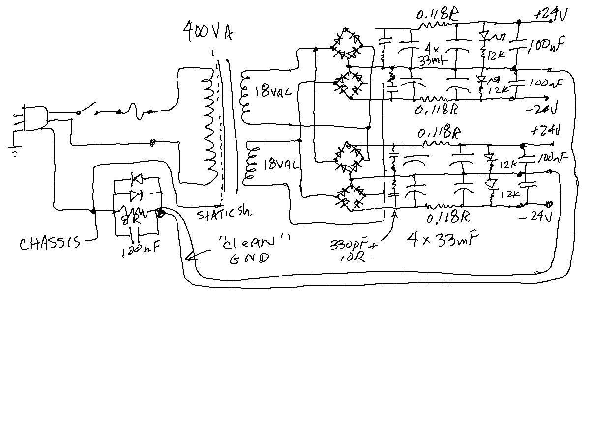
Here is my PSU setup:
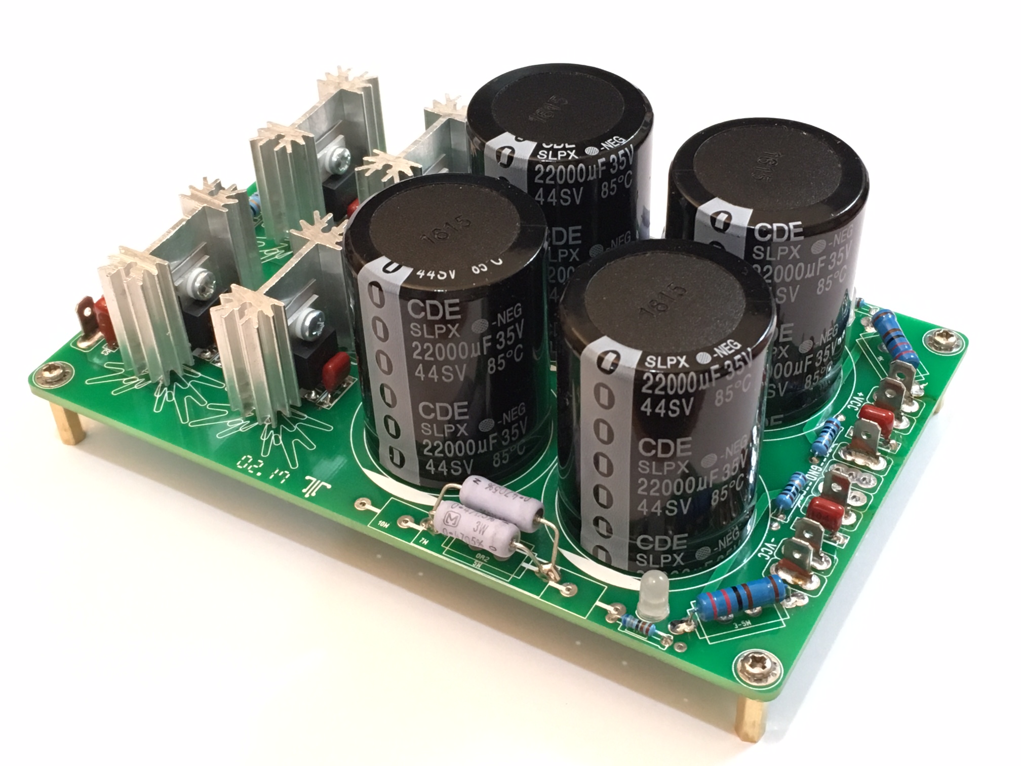
I have tried other PSU's, such as this one, and thee hum remains.
I did not have a hum issue when the above PSU was used with another amp (Aksa Quasi).
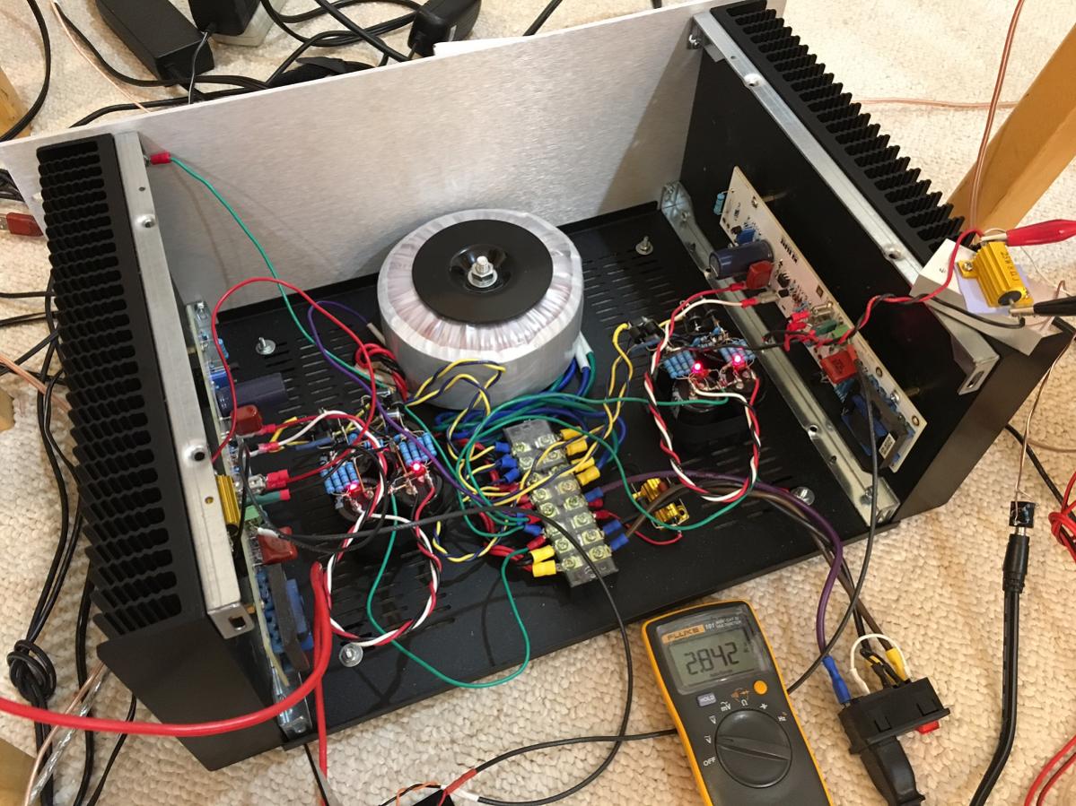
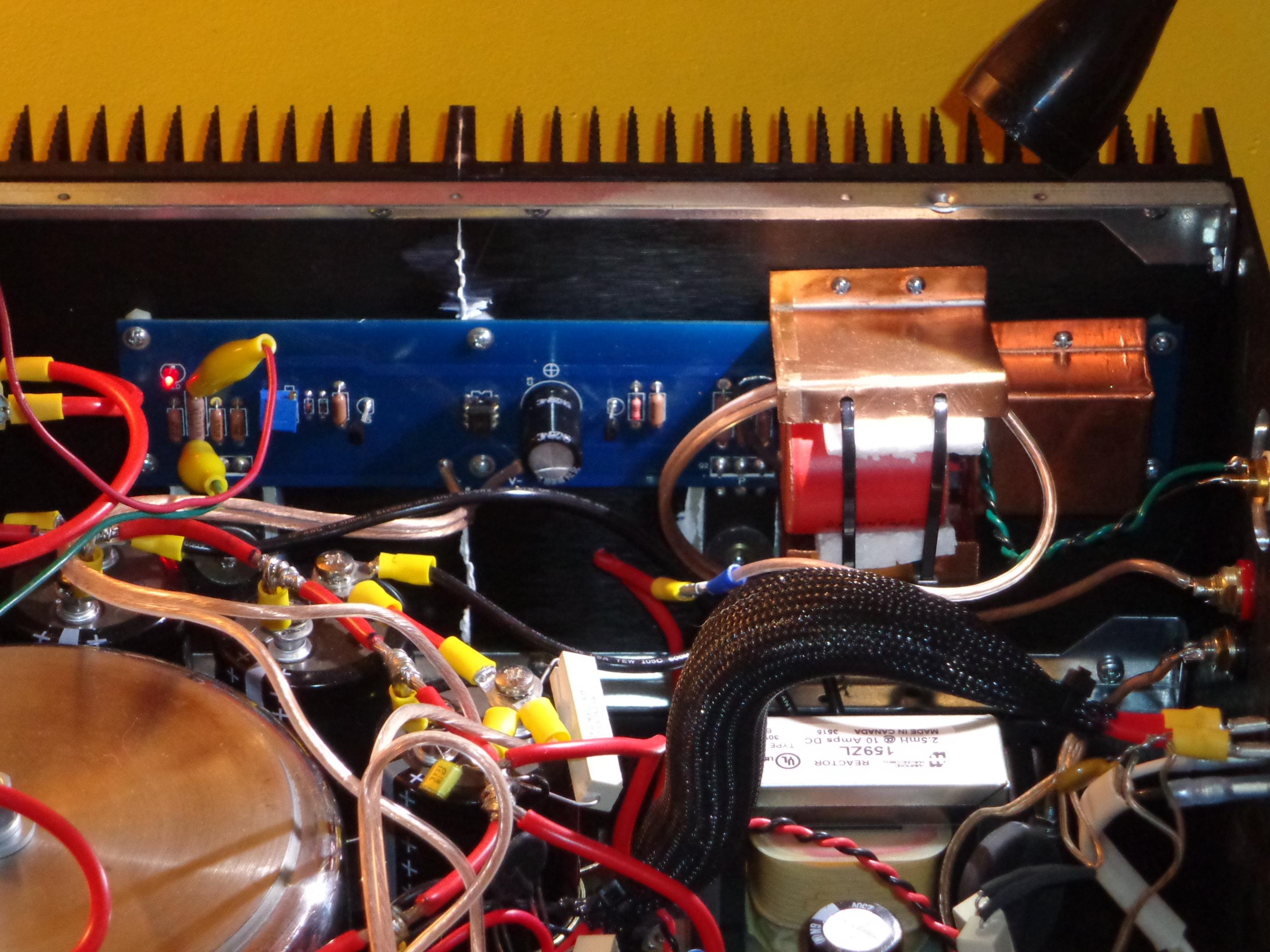
Here is my current M2 setup. Sorry for the messy wires, but they are twisted where possible.
Any help would be appreciated but I am about ready to scrap the whole big iron manly-man linear PSU for SMPS bricks.
So has anyone else had problems with this and could it be the signal transformer picking up EMI from the transformer?
Here is what the FFT is currently showing (the stuff to the left of 1kHz remains even when inputs shorted):
Here is my PSU setup:
I have tried other PSU's, such as this one, and thee hum remains.
I did not have a hum issue when the above PSU was used with another amp (Aksa Quasi).
Here is my current M2 setup. Sorry for the messy wires, but they are twisted where possible.
Any help would be appreciated but I am about ready to scrap the whole big iron manly-man linear PSU for SMPS bricks.
Last edited:
What brand type of transformer. A fellow friend on this forum had the same problem and changing transformer cured his problem.
Antek model AS-4218
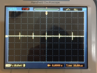
Here is what PSU output after CRC looks like. 10mV vertical and 10uS horizontal. There is 10mV spikes at circa 50kHz frequency. Probably mains contaminated with a SMPS somewhere.
Fairly clean PSU as far as linear PSU's go. At millisecond scale it shows 20mV 60Hz ripple under load of 1.3amps in each channel. No load the ripple is about 6mV.
Last edited:

Production M2's had a steel shield around the outside to take the radiation
down, plus the transformer was rotated to get minimum noise. This
with mu metal shield on the little transformers and their location at the
rear corners of the amp.
down, plus the transformer was rotated to get minimum noise. This
with mu metal shield on the little transformers and their location at the
rear corners of the amp.
I put a steel shield around the power transformer (literally a saucepan) and copper boxes on the little transformers (not mu metal but it was all I had) and I have no hum at all. Pics at post #1279.
I put a steel shield around the power transformer (literally a saucepan) and copper boxes on the little transformers (not mu metal but it was all I had) and I have no hum at all. Pics at post #1279.
Was there hum without the saucepan and Cu-metal shields?
My power and signal trafos are about in same exact places as yours. If that is a DIYA Dissipante 5U case, then same case as mine.
http://www.ebay.com/itm/Ultraperm-8...tal-Mu-Metal-Sheet-Audio-Shield/152491911889?
I like your stainless steel saucepot with a bolt through it. 🙂
Last edited:
Production M2's had a steel shield around the outside to take the radiation
down, plus the transformer was rotated to get minimum noise. This
with mu metal shield on the little transformers and their location at the
rear corners of the amp.
Mr. Pass,
What type of steel did you use, mild carbon or some sort of stainless? When you say, transformer was rotated, you mean the toroidal transformer is not cylindrically symmetric with regards to emitted EM field? Or do you mean rotated about an axis that is not the cylinder axis?
I actually have a handheld EM field meter that could be handy here (for power line field measurement etc.)
Something I have always done on FW amps is to rotate the toroid +/-60 deg
in operation, as one position will give minimum noise. Usually there is a
lobe of radiation, and pointing it at (or away) from the right spot is a big help.
I believe Mr. Pass is referencing rotation on axis such as that the toroid was a wheel. You can see an example of how one of his production units was rotated, but it sounds like each toroid will be unit for its "lobe" location.

Was there hum without the saucepan and Cu-metal shields?
My power and signal trafos are about in same exact places as yours. If that is a DIYA Dissipante 5U case, then same case as mine.
Didn't try it without the shields - they were the plan from the beginning. My case is a 4U case direct from modushop in Italy. Cheaper that way, though I had to drill it myself (Grimberg's boards didn't fit the universal mounting spec anyway).
- Home
- Amplifiers
- Pass Labs
- Official M2 schematic