OK, I replaced R4 with 8R2 and that brought DC offest at Edcor input to about 1mV in temperature equilibrium, but it was still over 5mV when cold and about 3mV when input shorted. So, to be sure, I added 220uF bipolar cap (Audio Note Kaisei) as recommended by Mark.
My M2 is playing music most of the day today and oh gosh, it sounds so good! I am glad I decided to build it. This one is a keeper 🙂
My M2 is playing music most of the day today and oh gosh, it sounds so good! I am glad I decided to build it. This one is a keeper 🙂
Hi, could someone recommend a preamplifier (with 5-6x gain) for M2? I need cca. 4Veff output. Thx a lot! Dee
Last edited:
Hi, could someone recommend a preamplifier (with 5-6x gain) for M2? I need cca. 4Veff output. Thx a lot! Dee
Maybe this would work for you...Salas DCG3. I don't have 1st hand experience, and it has a little lower gain, but I'm sure it's a really nice preamp.
Maybe this would work for you...Salas DCG3. I don't have 1st hand experience, and it has a little lower gain, but I'm sure it's a really nice preamp.
I'm building one now, it can have its gain set high enough to drive F4 if necessary. "standard" is 3x.
Russellc
I'm building one now, it can have its gain set high enough to drive F4 if necessary. "standard" is 3x.
Russellc
Keep us posted. I’m very curious.
I have one, very nice preamp. Worked very well with my M2, now works very well with my diy audio Sony vfet.
Hi, could someone recommend a preamplifier (with 5-6x gain) for M2? I need cca. 4Veff output. Thx a lot! Dee
AKSA's Lender Preamp with 40Vpp Output
Several folks have tried this combo and it works very well.
So I thought my M2 clone sounds great, then I added B1 with Korg Triode in front and it sounds even better! Maybe better than my 300B SET. Unbelievable...
Last edited:
Hi,
I am building the M2 using Tea Bag's boards. For C3 (3300uF), what would the minimum voltage rating be for this cap? I have 10 volt Elnas and 25 volt Nichicons. Would either of these work ok?
I also have Wima MKS 1uF or Wima MKP 0.1uF for bypass. Which would be better to use for the bypass?
Thanks,
Alan

I used 3300uF 50V capacitors from Cornell Dubilier in my M2(x). I reasoned that since I was ordering the parts from Mouser anyway, I might as well spend the extra 75 cents and purchase an extra margin of safety. I observe that the total supply voltage inside a standard M2 with a standard FirstWatt power supply is 46 volts. No matter how crazy the amplifier behaves during power-on, or how crazy it behaves during power-off, or how abnormally it operates when clipping, I felt that a cap rated higher than the total supply voltage, is going to be extra safe: 50V is more than 46V. After spending $80 for the chassis and $50 for the transformer and $40 for the fancy RCA Jacks + Speaker Binding Posts, I decided I could afford an extra two or three dollars for large capacitor safety margin too.
I chose WIMA 1.0uF film capacitors (box style; radial lead) to bypass the 3300uF electrolytics. On Tea Bag's thread you can see numerous examples of people using very exotic, very expensive axial lead film capacitors in this position. It might be a fun before-and-after listening experiment to try, if you don't mind spending 2 x $200 to audition the fancy capacitors.
I chose WIMA 1.0uF film capacitors (box style; radial lead) to bypass the 3300uF electrolytics. On Tea Bag's thread you can see numerous examples of people using very exotic, very expensive axial lead film capacitors in this position. It might be a fun before-and-after listening experiment to try, if you don't mind spending 2 x $200 to audition the fancy capacitors.
I use Panasonic FC 25V that I had at home and polycarbonate bypass capacitors.
Just need some 0R33 5W resistors, I will use Toshiba power mosfets. Plus I need to work on the amplifier case. I am almost there..🙂
Just need some 0R33 5W resistors, I will use Toshiba power mosfets. Plus I need to work on the amplifier case. I am almost there..🙂
Attachments
Just need some 0R33 5W resistors...
Is that a circuit modification? I don't see 0R33 resistors on the Official M2 schematic in post #1 of this thread.
Are you seeking to increase the MOSFET Class-A bias current by a factor of (47/33) = 1.42x ? If so remember that the heatsinks must dissipate (Ibias x (Vtoprail - Vbottomrail)) watts; increasing Ibias by 42% also increases heat dissipation by 42%
_
Attachments
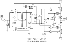
Is that a circuit modification? I don't see 0R33 resistors on the Official M2 schematic in post #1 of this thread.
Circuit modification from somewhere earlier in this thread, don't remember the exact post.
gaborbela said that he is using Toshiba Mosfets https://www.diyaudio.com/forums/pass-labs/281520-official-m2-schematic-314.html#post5597222.
I suppose that would be 2SK1530/2SJ201. ZenMod and generg were discussing about their performance into lower impedance speakers and suggested lowering the source resistors to 0R33 Ohms.
Yes, that leads to higher Iq ... I have built the exact same combination (Toshiba laterals and 0R33 source resistors), and my M2 is running at 1.82 amps / 24 V rails. The Toshibas have slightly larger casing (TO-264 ?), and have no problem dissipating the ~45W each. The heatsinks have to dissipate more heat as well, of course, but a 4U/400 case will cope with that very well in a Canadian or Central European climate 😀.
Best regards, Claas
Hi,
I also have Wima MKS 1uF or Wima MKP 0.1uF for bypass. Which would be better to use for the bypass?
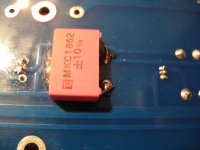
My budget favourite ist WIMA MKP10 polypropylen capacitors. Used them as coupling capacitors in almost all my builds.
+1 for ZenMods MKCs, as well.
I never liked the sound of the MKS. I still have a lot of them, bought when refurbishing vintage gear, but rarely use them now ...
Best regards,
Claas
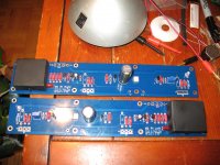
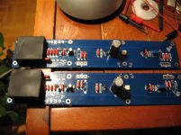
Yet another M2 clone
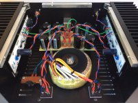
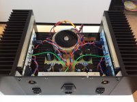
Finally bringing up my M2 implementation... as you can see, Tea Bag PCBs. A very nice solid product if you are reading. A DIY aluminium chassis (slots all millled with hand router!). 300VA transformer and some nice big sinks from RS - 177AB1500B @ 0.23C/W. Tea Bag BOM. PSU hardwired under proto board with 2mm^2 tinned copper wire.
Anyway, biasing no problems using increased value of R7 as per Tea Bag. Both outputs within 5mV of 0V DC. Tiny amount of hum, volume control independent.
Driving via B1 buffer unmodified. No JFETs at input to M2 - wired straight into Edcor. 1st surprise... huge reduction in volume compared to my ACAs. Mmm.. I figure that's the 1K resistor on output of B1 driving about 600R. I forgot about the 600R vs 6K input impedance thing! Will get rid of that 1K tomorrow as per Zen Mod suggestion. The sound is uninvolving though at the moment. Big suckage in evidence maybe? Hopefully better things to come.
Attachments
- Home
- Amplifiers
- Pass Labs
- Official M2 schematic