PRR and Mark,
"Volts equals Amps times Ohms."
"Volts equals Amps times Ohms."
"Volts equals Amps times Ohms."
"Volts equals Amps times Ohms."
"Volts equals Amps times Ohms."
........ wake up Phil
My now wife who was my girlfriend at the time always had to wake me up during the middle of the night when I was in my basic electrical theory class; I couldn't stop muttering "Volt's equals Amps times Ohms" while in my sleep.
I went to a trade school to become an electrician when I was in my early 20's, this was in 2006 or 2007. My first instructor had been teaching since 1969. On the first day of class he told us all, "Anyone can get an "A", I've given them out four times. But as of right now, you've all got an "F" and are failing." Every assignment was on a large spreadsheet that he had printed out on a plotter; it was probably three by four feet. Everyone who was in the class had their name on a vertical column on the spreadsheet. Everyone knew where everyone else stood in the rankings.
The instructor was "old school" by today's standards. He didn't care about feelings. Everything was straight forward and up-front with him. When he started teaching, only one in three would graduate. Their degree meant something in those days. The instructor didn't care about published graduation rates, he wanted our degrees to mean something.
For every calculation, we always had to start with the fundamental Ohm's law:
E=I*R
Then we would transpose it for the calculation:
I=V/R
I wrote down E=I*R so many times that I would mutter it in my sleep.
I never before appreciated math, because I never had anywhere that I could apply it. Once I found a place to apply it, I fell in love with it. diyAudio is my hobby that keeps me from going insane while using math in my current career. Forward and inverse kinematic calculations of a serial link robot will drive anyone nuts, especially if they were hired to spend a lot of their time doing electrical and mechanical assembly.
I calculate tube dissipation by calculating the current through the cathode bias resistor.
Volts = Amps * Ohms
therefore
Amps = Volts / Ohms
Once I know the current through the tube, I can multiply it by the voltage across the tube's cathode to plate.
Watts = Volts * Amps
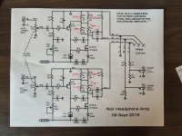
I've taken some measurements and done some calculations, but I don't know if I am going down the right path. I think each of my output FETs has 314mA going through it for a total dissapation of 7.13408 watts.
Can someone help guide me through the math? I've attached pictures of my measurements and calculations. All of my calculations are based off speculation on what I know about single ended vacuum tube circuits.
I appreciate anyone who takes the time to read this.
Thanks agian,
-Phil
"Volts equals Amps times Ohms."
"Volts equals Amps times Ohms."
"Volts equals Amps times Ohms."
"Volts equals Amps times Ohms."
"Volts equals Amps times Ohms."
........ wake up Phil
My now wife who was my girlfriend at the time always had to wake me up during the middle of the night when I was in my basic electrical theory class; I couldn't stop muttering "Volt's equals Amps times Ohms" while in my sleep.
I went to a trade school to become an electrician when I was in my early 20's, this was in 2006 or 2007. My first instructor had been teaching since 1969. On the first day of class he told us all, "Anyone can get an "A", I've given them out four times. But as of right now, you've all got an "F" and are failing." Every assignment was on a large spreadsheet that he had printed out on a plotter; it was probably three by four feet. Everyone who was in the class had their name on a vertical column on the spreadsheet. Everyone knew where everyone else stood in the rankings.
The instructor was "old school" by today's standards. He didn't care about feelings. Everything was straight forward and up-front with him. When he started teaching, only one in three would graduate. Their degree meant something in those days. The instructor didn't care about published graduation rates, he wanted our degrees to mean something.
For every calculation, we always had to start with the fundamental Ohm's law:
E=I*R
Then we would transpose it for the calculation:
I=V/R
I wrote down E=I*R so many times that I would mutter it in my sleep.
I never before appreciated math, because I never had anywhere that I could apply it. Once I found a place to apply it, I fell in love with it. diyAudio is my hobby that keeps me from going insane while using math in my current career. Forward and inverse kinematic calculations of a serial link robot will drive anyone nuts, especially if they were hired to spend a lot of their time doing electrical and mechanical assembly.
I calculate tube dissipation by calculating the current through the cathode bias resistor.
Volts = Amps * Ohms
therefore
Amps = Volts / Ohms
Once I know the current through the tube, I can multiply it by the voltage across the tube's cathode to plate.
Watts = Volts * Amps
I've taken some measurements and done some calculations, but I don't know if I am going down the right path. I think each of my output FETs has 314mA going through it for a total dissapation of 7.13408 watts.
Can someone help guide me through the math? I've attached pictures of my measurements and calculations. All of my calculations are based off speculation on what I know about single ended vacuum tube circuits.
I appreciate anyone who takes the time to read this.
Thanks agian,
-Phil
Attachments

This is not an electric bill. You do not need 4-place numbers. And they distract you.
I do not understand your spreadsheet, and I doubt you do.
Somehow you have got double the current (did you treat series resistors as parallel?).
And you seem to be looking for supply voltage, when you really want tube/transistor voltage. Even in a transformer-coupled tube amp these are not the same. In a resistance-coupled amp the resistor often takes half the available voltage.
PRR,
Thanks, like I said, it's been over a decade since I was in school for this stuff.
The four resistor combination threw me for a loop. I was adding up the current from each resistor. I see now that I really only needed to calculate the current through the R27/28 parallel pair.
Also, forgot about the total voltage drop over each part of the series chain.
I think I've got it right now. Mind being so gracious and checking again?
Oh, and as to the decimal points, I'll always take whatever data I can get. I work with high precision custom robots and machine tools. Try measuring 15 arc seconds of rotation from 30 meters away. I never truncate or round; at the end of the day, data storage is cheap, but the money paid for the Metrology to get those numbers is not.
If I had the room to haul around a Fluke 45 with me I would, but then I wouldn't have room for my awesome new Noir 😉
Thanks again for the help, this is why I love diyAudio.
And yet you clearly have 10% differences in "identical" resistors. Electronics is almost never an arc-second job. Resistors are sold with 10% tolerances because we can make that work, MUCH cheaper than 0.001% parts.Try measuring 15 arc seconds of rotation from 30 meters away. I never truncate or round; at the end of the day, data storage is cheap
And in desk-checking, "data storage" is a sliver of brain or the back of a matchbook. Long numbers are, for me, mind-numbing.
Precision:
You don't need an "exact" number for dissipation. Up to 1 Watt, no sink, over 10 Watts, big sink. In between you go by size and price.
One place precision may need thinking: the ratio R25+R26/R27+R28 is also part of the audio gain. The voltages you are reporting suggest that R25+R26 is 10% bigger than R27+R28, which may be a gain of 1.9 rather than 2.0. We can usually separate "precision" and "power" with negative feedback. Here Mark used power parts AS the NFB network, a very efficient and thrifty use of parts. (Avoids the NFB network loading the amp.) However you seem to have got unlucky with tolerances.
I'm having to bite my tongue to try and keep things cordial. I'm just trying to find out if I am doing the math correctly.
I am currently on the road in a hotel room, I don't have my thermal couple with me, so I can't do any thermal compensation. The factory I work in is around 95°F and I much prefer working in 45° cold rooms. That being said, my hotel room is kept at 65°F during the night when I have the time to try and learn from a hobby I enjoy. Opening up the warm sealed enclosure in my chilly room allows it to cool rapidly, I'm guessing my oversized heat sinks help with this I try to take measurements as quickly as possible, but I am also careful not to short anything out with my probes.
The voltages start falling as soon as I open the case. The first measurement I always take qualitatively is with my pinky on the back of the heat sink. I realize none of this is I ideal, but I'm simply just asking if my math is using valid calculations.
I was obviously incorrect the first go round. I thanked you for pointing me in the right direction. Can you please just answer my question?
Anyone?I'm having to bite my tongue to try and keep things cordial. I'm just trying to find out if I am doing the math correctly.
I am currently on the road in a hotel room, I don't have my thermal couple with me, so I can't do any thermal compensation. The factory I work in is around 95°F and I much prefer working in 45° cold rooms. That being said, my hotel room is kept at 65°F during the night when I have the time to try and learn from a hobby I enjoy. Opening up the warm sealed enclosure in my chilly room allows it to cool rapidly, I'm guessing my oversized heat sinks help with this I try to take measurements as quickly as possible, but I am also careful not to short anything out with my probes.
The voltages start falling as soon as I open the case. The first measurement I always take qualitatively is with my pinky on the back of the heat sink. I realize none of this is I ideal, but I'm simply just asking if my math is using valid calculations.
I was obviously incorrect the first go round. I thanked you for pointing me in the right direction. Can you please just answer my question?
I just want to know if my math is valid.
Thanks.
Mark, for us unfortunate folks in the E.U. where tariffs apply for stuff entering from U.S. do you have any experience in shipping the PCB and getting it through without being stopped at the customs?
Or anyone living within the E.U. and ordering Mark's PCB?
Or anyone living within the E.U. and ordering Mark's PCB?
Last edited:
I transferred ownership of Noir's Gerber files to the diyAudio Store. Buying from them is the only way I'm aware of, to get a brand new, never-before-owned, Noir PCB. Maybe there are people who bought a Noir PCB but never got around to building the amp; maybe they'd be delighted to sell or give their pristine but "pre owned" PCB to you. You could ask in this thread or in the Swap Meet. The key acronym to put in the title is WTB -- Want To Buy .
Thanks for the reply Mark.
I am not very optimistic that many E.U. folks would want to part with their Noirs, but hey, if there's anyone out there, I am interested!
I am not very optimistic that many E.U. folks would want to part with their Noirs, but hey, if there's anyone out there, I am interested!
For anyone ordering items from the store into countries that charge duty or VAT, I recommend using the shipping service described as DHL Express "Delivered Duties Paid". All these shipments are "electronic" manifest, and shipments fly straight through customs with both duties and VAT pre-paid. Usually takes 3-5 business days from ordering to it turning up at your door.Mark, for us unfortunate folks in the E.U. where tariffs apply for stuff entering from U.S. do you have any experience in shipping the PCB and getting it through without being stopped at the customs?
Or anyone living within the E.U. and ordering Mark's PCB?

Please send me a PM. (Can't figure out how to do itself)Thanks for the reply Mark.
I am not very optimistic that many E.U. folks would want to part with their Noirs, but hey, if there's anyone out there, I am interested!
We made de PCB ourself, for the same reason.
Shipping costs from US to EU, is insane.
I have 2 PCB's left.
PMs "Conversations" are not enabled until moderators see a record of good public messages. This hinders spammers. (I know another forum where thousands of spammy PMs were posted overnight.)Please send me a PM. (Can't figure out how to do itself)
As you have guessed, @evonimos (a quasi-prolific poster) can probably PM you to get a Conversation started.
Ah, that explains, and make good sense.PMs "Conversations" are not enabled until moderators see a record of good public messages. This hinders spammers. (I know another forum where thousands of spammy PMs were posted overnight.)
As you have guessed, @evonimos (a quasi-prolific poster) can probably PM you to get a Conversation started.
I'll wait for a PM from him then.
Thanks.
Another Noir is working. Thank you Mark for this great design.
I made a wood enclosure, has been very easy thanks to the front and back panel that comes together with pcb. No metal drilling or cutting, nothing, just usual woodworking.
The BOM is very helpful too. I used it complete except the potentiometer, the Alps one is too expensive and change it.
I'll tell my mistakes, maybe help others:
1. I plugged the heatsink in small transistors before soldering. And soldered one wrong. Of course, this channel didn't bias correctly. Luckily I could desolder and fix it. It's very easy to do the same mistake because the heatsink covers the flat in the body. Beware!.
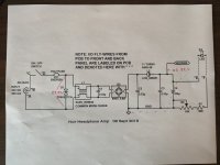
2. I connected wrongly the headphone socket wires. Better follow exacty the nice pictures in the Build Guide.
Once my mistakes are fixed, it bias and plays nicely.


I made a wood enclosure, has been very easy thanks to the front and back panel that comes together with pcb. No metal drilling or cutting, nothing, just usual woodworking.
The BOM is very helpful too. I used it complete except the potentiometer, the Alps one is too expensive and change it.
I'll tell my mistakes, maybe help others:
1. I plugged the heatsink in small transistors before soldering. And soldered one wrong. Of course, this channel didn't bias correctly. Luckily I could desolder and fix it. It's very easy to do the same mistake because the heatsink covers the flat in the body. Beware!.
2. I connected wrongly the headphone socket wires. Better follow exacty the nice pictures in the Build Guide.
Once my mistakes are fixed, it bias and plays nicely.
Inside, The box is made of just 8 pieces of 15mm plywood.

Can i substitute Kemet choke SU9V-R05034 (out of stock) with SU9VF-05030 ?
I am going to use SMPS DC filter from the DIYAudio store .
Could the choke be omitted and replaced with jumpers ?
I am going to use SMPS DC filter from the DIYAudio store .
Could the choke be omitted and replaced with jumpers ?
I bought the Noir pcb along with the chassis , an smps dc filter and a super regulator pcb from the Diyaudio store .. just to let you know i was charged 39€ vat and customs fees here in Greece using the DHL Ecommerce packet plus shipping . The DHL Express shipping service would have cost me 30€ more .. way too expensive ...For anyone ordering items from the store into countries that charge duty or VAT, I recommend using the shipping service described as DHL Express "Delivered Duties Paid".
Is there anyone to assist me with my previous post ?
thanksCan i substitute Kemet choke SU9V-R05034 (out of stock) with SU9VF-05030 ?
I am going to use SMPS DC filter from the DIYAudio store .
Could the choke be omitted and replaced with jumpers ?
- Home
- Amplifiers
- Headphone Systems
- Noir, a two transistor headphone amp: class-A, single ended, 150mA bias