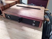
I finally finished my Noir build! This is my first solid state and circuit board based build. I have to say, I spent a considerably longer time dealing with a home build chassis than I did stuffing the boards.
Thanks to the great build instructions, the chassis build out was easily planned, and the circuit board assembly went smoothly.
I'll post a couple finished photos here. I always keep a build photo log, if you are interested.
Thanks to all here for what you do, lots of great information and community going on here!
Attachments
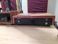


Nice woodwork!I finally finished my Noir build! This is my first solid state and circuit board based build. I have to say, I spent a considerably longer time dealing with a home build chassis than I did stuffing the boards.
Thanks to the great build instructions, the chassis build out was easily planned, and the circuit board assembly went smoothly.
I'll post a couple finished photos here. I always keep a build photo log, if you are interested.
Thanks to all here for what you do, lots of great information and community going on here!
Yup, casing is always the longest part of the process for me. That's one of the things I loved about the Noir, the case was almost completed for me!

Have a look at posts #127, 128, 129 in this thread, for ideas about alternative ferrite cores. Wind as many turns as you are able to do comfortably, and be happy.
The PCB includes a footprint for the E-153 in both thru hole AND surface mount packages. My first preference would be to use the designer's chosen part (E-153) in surface mount
link to EU Mouser
My second choice would be to try the E-183 and hope for the best.
Mark,
Do you have any idea as to what may happen if the E-183 is substituted for the E-153?
I know this will be a 20% increase in current, but can this be compensated for with the bias pot?
Thanks,
-Phil
Sure, go ahead and try both the E-123 (12 mA) and the E-183 (18 mA) since the E-153 (15 mA) is out of stock and won't be replenished for two weeks. Mouser says March 11th.
Nothing can change the current flowing through a Current Regulator Diode; the Noir bias potentiometer sets the output voltage operating point, to maximize signal swing before clipping.
Nothing can change the current flowing through a Current Regulator Diode; the Noir bias potentiometer sets the output voltage operating point, to maximize signal swing before clipping.
My board is mostly stuffed. I have all of the needed parts in hand.

It will fit into this chassis I saved from the scrap pile at work. It will be (REALLY) tight, but doable. The 170mm x 100mm PCB mounting pattern is slightly larger than the bottom plate of the enclosure, but it does fit. I am hoping I can get away with the increased heat caused by a sealed enclosure by changing out the heat sinks to a 2.5" model. The taller enclosure also allows for my taller output caps to be conventionally mounted.


I now have the E-153 CRD as well. I have been looking into learning LTSpice, but I have enough other stuff to keep me busy right now. Can anyone point me to a simulation with different parts/current sources? I have looked through both this and the T2 thread, but it's a lot to go through and I haven't found exactly what I am looking for.
I did see pictures in the DIYAudio store, where someone used screw retaining terminal blocks for the various inputs. I would like to use these as well, it should help with the confined space.
I don't have my board in front of me, does anyone know the pitch of the various input pads? It looks like all of the signal pads are the same, but the DC input may be slightly wider. I have tried to calculate the pitch by scaling from a straight on photo of the bare board, but my calculations don't match a standard pitch.
I am very eagerly awaiting to power this up. Thanks again Mark for all of your great contributions over the years.
It will fit into this chassis I saved from the scrap pile at work. It will be (REALLY) tight, but doable. The 170mm x 100mm PCB mounting pattern is slightly larger than the bottom plate of the enclosure, but it does fit. I am hoping I can get away with the increased heat caused by a sealed enclosure by changing out the heat sinks to a 2.5" model. The taller enclosure also allows for my taller output caps to be conventionally mounted.
I now have the E-153 CRD as well. I have been looking into learning LTSpice, but I have enough other stuff to keep me busy right now. Can anyone point me to a simulation with different parts/current sources? I have looked through both this and the T2 thread, but it's a lot to go through and I haven't found exactly what I am looking for.
I did see pictures in the DIYAudio store, where someone used screw retaining terminal blocks for the various inputs. I would like to use these as well, it should help with the confined space.
I don't have my board in front of me, does anyone know the pitch of the various input pads? It looks like all of the signal pads are the same, but the DC input may be slightly wider. I have tried to calculate the pitch by scaling from a straight on photo of the bare board, but my calculations don't match a standard pitch.
I am very eagerly awaiting to power this up. Thanks again Mark for all of your great contributions over the years.
Just finished my Noir, sounds really good, but won't boot my Whammy out of my main rig. But Noir will get to do office duty 😎 Very nice little amp, but took a while to source the E-153's. Tried with some other 15mA constant current diodes off AliBaba, but they did not work. Mainly cause they did work as 15mA constant current limiters / sources at all. (And was SMD) Took a while to work out what went wrong there. But got hold of real E-153's and now all is good! (Mouser got a few of them back in stock now!)
Attachments
I'll have to watch it.Class A in a sealed metal box with no ventilation?
I did increase the heatsinks to 2.5" on the output devices. I was able to let it idle with the lid closed for an hour, and I could still easily touch the heatsinks. They were warm, but not hot.
I did touch up the bias fifteen minutes into the test.
How will the load impedance affect dissipation? Is it correct to assume that sitting idle with no output is the worst case dissipation? Would it be any different with 32 or 300 ohm headphones hooked up, but not playing?
I plan on doing more thorough testing with a thermocouple, but so far the larger heatsink seem to be working as I had hoped.
I can always add ventilation if I find that I need it. Fingers crossed that I don't. Not that it would be difficult, I just prefer the current look.
Noir's power dissipation is constant, whether an input signal is present or not. {This assumes you're not driving the output into clipping -- but that would be very, very loud}
Its power dissipation is also constant whether the output load is high impedance (e.g. driving the preamp-out RCA jacks) or low impedance (30 ohm headphones).
Its power dissipation is also constant whether the output load is high impedance (e.g. driving the preamp-out RCA jacks) or low impedance (30 ohm headphones).
Does anyone know of any good replacement parts for the filter choke (SU9V-R05034)?
I also grabbed me some of the universal PSU board and figured id use half a kit for this project, any tips on how much capacitance that will be sufficient for this?
I also grabbed me some of the universal PSU board and figured id use half a kit for this project, any tips on how much capacitance that will be sufficient for this?
Hi Sepe, I found this one, seems pretty similar in specks and did drop right in on the PCB, and works fine as far as I can hear in my Noir. https://no.mouser.com/ProductDetail/871-B82730U3751A020
Thank you for the help!Hi Sepe, I found this one, seems pretty similar in specks and did drop right in on the PCB, and works fine as far as I can hear in my Noir. https://no.mouser.com/ProductDetail/871-B82730U3751A020
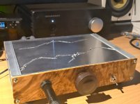
It's ALIVE!
This thing is DEAD quiet with the inputs shorted. I'm sure the "grounded" enclosure helps. It's weird to have a chassis that is not at ground potential.
I over torqued the nut on the power switch during installation and snapped the barrel off, so it is bypassed for now. I also snapped the LED off it's leads while trying to fit it. Oh well, I can run for now without either of those.
The heatsinks are only slightly warm when the enclosure is completely shut and the amp is powered up for 1+ hour.
When I was adjusting the bias, I had to drape a towel over the slightly opened enclosure to keep the heat in. My meter probes would not allow it to be fully shut.
Can someone please explain the math or post a formula to calculate the output FETs dissipation vs. the voltage drop across the resistors?
I know how to calculate dissipation in a single ended tube circuit, but it's been over a decade since I've done any solid state stuff.
With my larger heatsinks, I think I may be able to bias this amp a little hotter than prescribed, but I would like to know how to calculate where I am actually operating the amp at.
This thing sounds absolutely amazing. I am currently away from home without my best headphones, I can't wait to get back and do some critical listening with my good cans.
Thanks again to Mark and the DIY Audio team for making this available.
Attachments
So how do you do a tube?explain the math or post a formula to calculate the output FETs dissipation vs. the voltage drop across the resistors? I know how to calculate dissipation in a single ended tube circuit,....
Measure voltage across it.
Measure current through it (usually by measuring voltage across a series resistor).
Multiply.
________________
However, in this plan, if you used the specified power resistor values, it can't pull more than about 8 Watts total (all in the resistors), non-functional. Or about 2 Watts in each of transistor and resistor-quads (4W total). So the transistor wants a sink for more than momentary use, but it does not have to be any Paris–Dakar Rally heat radiator.
Mathematics-averse people may prefer to pay USD 14 for this piece of laboratory gear . Measure AC power and make the conservative overestimate that DC power equals AC power minus zero. I.e. zero dissipation in the wall wart.
Sales page suggests that watts readings include one digit after the decimal point. I imagine some people find that preferable to deriving and solving equations.
edit- fixed link
Sales page suggests that watts readings include one digit after the decimal point. I imagine some people find that preferable to deriving and solving equations.
edit- fixed link
Last edited:
- Home
- Amplifiers
- Headphone Systems
- Noir, a two transistor headphone amp: class-A, single ended, 150mA bias