Any idea if/when the store is going to get the case back in stock by chance? Or pointers for alternatives?
Buy it from @Gianluca 230x170mm 1U Galaxy.
https://modushop.biz/site/index.php?route=product/product&path=33_286&product_id=243
https://modushop.biz/site/index.php?route=product/product&path=33_286&product_id=243

Hello,
I built a first version of the Noir on breadboard and everything seems to work in general, thank you for providing the information for this project!
I have some questions:
-Is it possible to use +24V and GND (insted of GND and NEGPWR)? This way the circuit could also be used with non-isolated power supplys.
Acc. my simulation in LTSpice it should work when R11 (R31/R81 in the original circuit) is connected to GND:

I am curious why is it using this topology anyway?
-Is there a recommendation for a ready made component for L2/has anyone measured the inductance?
Thank you very much! 🙂
I built a first version of the Noir on breadboard and everything seems to work in general, thank you for providing the information for this project!
I have some questions:
-Is it possible to use +24V and GND (insted of GND and NEGPWR)? This way the circuit could also be used with non-isolated power supplys.
Acc. my simulation in LTSpice it should work when R11 (R31/R81 in the original circuit) is connected to GND:
I am curious why is it using this topology anyway?
-Is there a recommendation for a ready made component for L2/has anyone measured the inductance?
Thank you very much! 🙂
Why the supply is inverted - (from post #1)
As for L2, the ready-made object is the ferrite core, the wire is simple enough to source yourself. 🙂
Fig 2 is the Noir schematic. Compared to Figure 1, the device polarities have been reversed. Now the input transistor is P-type and the output transistor is N. This is advantageous because N-channel MOSFETs have a gain-per-unit-silicon-area which is proportional to electron surface mobility. P-channels' gain is proportional to hole surface mobility, and is 2-3X less. All we need to do is flip the power supply upside down, and we get 2-3X higher gain per unit capacitance. An easy decision. Thus Noir uses a positive-ground, negative-supply arrangement, with the supply rail "NEGPWR" at about -22 volts. Just like germanium transistor radios in the late 1950s.
As for L2, the ready-made object is the ferrite core, the wire is simple enough to source yourself. 🙂
@florian911 , suppose for a moment that the SMPS noise filter in Noir is less than perfect. Suppose that some nonzero amount of noise is present, riding atop the 24VDC supply. Look at the schematic of #504. Look at C3. Look at R7 & R8. Ask yourself what happens if the hypothetical +24V supply is noisy.
In your LTSPICE .TRANsient simulation, set the input "V1" to zero millivolts of input signal, and set the supply "V2" to be a 1 volt peak-to-peak square wave at 2 kHz, riding atop 24 volts of DC. Now you have an amplifier whose signal input is zero; is its signal output also zero?
_
In your LTSPICE .TRANsient simulation, set the input "V1" to zero millivolts of input signal, and set the supply "V2" to be a 1 volt peak-to-peak square wave at 2 kHz, riding atop 24 volts of DC. Now you have an amplifier whose signal input is zero; is its signal output also zero?
_
Attachments
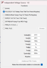
set the supply "V2" to be a 1 volt peak-to-peak square wave at 2 kHz, riding atop 24 volts of DC
Thanks, so this is probably what you mean, right? V(n001) is the voltage over R14 (load).
(original version on top)
Sure, I just let it out for simplicity. Lets hope that I don't have a 1V (p-p) ripple 😉 (I had to useda substitute PSU by Meanwell, the one in the Mouser BOM is not available in the EU), but at the moment I don't have an oscilloscope here to measure (has anyone experiences with the Picoscope 2204A? Probably buying that).suppose for a moment that the SMPS noise filter in Noir is less than perfect
If my understanding of above simulation is correct, the version with NEGPWR is more tolerant to noise on the supply, nevertheless I would like to filter it out as good as possible. Do you have a suggestion in which direction the CLC-filter at the power supply section should be optimized? Like a start value of inductance? Or could an additional LDO be beneficial?
Sure, but I would prefer a solution which can be reproduced a bit better/does not rely on spare parts laying around 🙂As for L2, the ready-made object is the ferrite core, the wire is simple enough to source yourself. 🙂
Unfortunately BC516-D27Z is End of Life, would maybe ZTX705 be an alternative?
I also am a bit concerned about the 3300µF electrolytic, is it worth it to upgrade for exampla to a Nichicon from their "Audio Grade Electrolytic Capacitors" series like UFW1V332MHD? Or use some low-ESR type with 10kh lifetime like Panasonic EEU-FR1E332? Or a Mundorf M-Lytic?
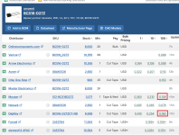
There are currently 10,000 BC516-D27Z available between just Digikey and Mouser. No doubt many others out there also.
I wouldn't get too excited about fancy caps - Audio grade is unnecessary for power supply smoothing duty.
I tend to favour the EEU series with the longer life and low ESR, but usually the final decision is based upon price versus datasheet attributes such as temp rating / life. Sometimes other recognisably quality brands and product ranges have specials that fits the bill just fine.
At the moment its still 100% Noir (except not available wallwart) 😉I'm just brainstorming some ideas.Good luck with your no-longer-a-Noir design!!
These two are the best available sources for private persons and 10k transistors is not really that much, isn't it? But of course I am not sure where this type is still used. It would only be sad if I build it now with BC516 and in a few month if I would build another one for a friend I would have to think about a redesign (e.g. ZTX705 is not pin compatible).There are currently 10,000 BC516-D27Z available between just Digikey and Mouser.
Sure, I would only change C5 in above schematic but only if it's really worth it.I wouldn't get too excited about fancy caps - Audio grade is unnecessary for power supply smoothing duty.
A lot of diyAudio members routinely buy 100-piece lots of TO-92 transistors, especially PNPs and PJFETs and PMOSFETs. It seems that semiconductor manufacturers are phasing out thru-hole P types right now, and may or may not phase out the complementary thru-hole N types at some future date. Spend twenty dollars for peace of mind, while you still can. Call it cheap insurance.
_
_
Attachments
I honestly wouldn't overthink things.These two are the best available sources for private persons and 10k transistors is not really that much, isn't it? But of course I am not sure where this type is still used. It would only be sad if I build it now with BC516 and in a few month if I would build another one for a friend I would have to think about a redesign (e.g. ZTX705 is not pin compatible.
You could buy 10 now to be on the safe side - that would only cost $2.20USD. 100 would be a little above $10USD.
Cheap insurance rather than trying an untested alternative that may or may not have the desired outcome in terms of design performance.
Thanks, I will do that.
Because of the switch on thump I would like to combine the Noir design with DIY Audio speaker-turn-on-delay-and-dc-protector-board. Do you have a suggestion how to connect it, +24V(Prot) to GND(Amp) and GND(Prot) to NEGPWR(Amp)? Or the protection board directly to the 24V PSU? I would like to use one wallwart for amp + protection and for recognizing DC voltage in the signal GND of the protection board has to be connected the amp.
Because of the switch on thump I would like to combine the Noir design with DIY Audio speaker-turn-on-delay-and-dc-protector-board. Do you have a suggestion how to connect it, +24V(Prot) to GND(Amp) and GND(Prot) to NEGPWR(Amp)? Or the protection board directly to the 24V PSU? I would like to use one wallwart for amp + protection and for recognizing DC voltage in the signal GND of the protection board has to be connected the amp.
So i managed to get the noir built 😉 i need to spend some time actually listening to it but it was able to drive my lcd-x to painful listening levels! It’s dead quiet at full volume and no input so i guess i did at least something right!
Everything is stock. Probably going to keep it that way unless there are any neat or suggested changes?
The only missing part is the volume knob. For the price I’m very likely to just draw and 3d print a knob 😉 0.30 with of plastic or 10 plus shipping. Maybe buy one with some future parts buy- we’ll see!
Thanks @Mark Johnson
I just unplug the headphones from the Noir front panel, before flipping the toggle switch to OFF. Since there's no remote control, I'm usually within arm's reach of Noir anyway, so I can fiddle with the volume knob. Very quickly it becomes automatic; an ingrained muscle memory. Step 1: unplug the 'phones. Step 2: switch to OFF.
However, if you insist upon experimenting with a speaker delay relay PCB connected to Noir, I recommend performing your first experiments using a music signal source that has no connection to the AC mains, i.e., a battery powered source. That way, if your choices of connections to the relay board accidentally result in a short circuit between Noir's -24V power supply and the source's ground, everything probably has a better chance of survival.
DC protection is not a particularly troublesome issue when the headphones are AC coupled to the amp, as in Noir. The same goes for other AC coupled amps here on this site, including Amp Camp Amp, Zenductor, Zenductor II, Amp Camp Preamp, lottery VFET power amp, Starving Student II headphone amp, ACA mini, etc. None of those include DC protection either.
That protection is not suitable for headphone amplifiers. Only power amplifiers.Because of the switch on thump I would like to combine the Noir design with
I know but I would like to give one unit away as a present and I fear that will lead to problems 🤐Step 1: unplug the 'phones. Step 2: switch to OFF.
@Mark Johnson Ok, I left out the DC protection part and connected the relay circuit to the same 24V (isolated) PSU as the Noir, that shouldn't lead to problems.
@Julian RO Why is that? Seems to work at least for startup at the moment, switching off is not fast enough (yet), there is still a peak of around 100ms:
Red: Output of the amp (switching on and off)
Blue: Output to headphone/after relay
- Home
- Amplifiers
- Headphone Systems
- Noir, a two transistor headphone amp: class-A, single ended, 150mA bias