As Damir already suggested, I also thinks that is better not use C6,C8 and use some 330 ohms base stopers at Q21/Q22 .
those caps bootstrap the CCS to the rail, but as the phase is opposite the result is flat.
this is a gerhard invention, and practise has shown better CCS performance.
But better would be a depletion supertex cascoded CCS.
this is a gerhard invention, and practise has shown better CCS performance.
But better would be a depletion supertex cascoded CCS.
Ok, have to take a better look, but at first look it seems that adding such a high capacitor value will decrease the feedback loop of the ccs, and will decrease the output impedance of the ccs, but in this position the ccs output impedance is not very important anyway. and those caps will for sure make the ccs more stable 🙂
the depletion mosfets from infineon have a very low Vth variation, You should check those.
the depletion mosfets from infineon have a very low Vth variation, You should check those.
those caps bootstrap the CCS to the rail, but as the phase is opposite the result is flat.
this is a gerhard invention, and practise has shown better CCS performance.
But better would be a depletion supertex cascoded CCS.
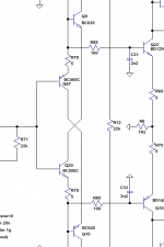
I was talking about C21, C33 in .asc file presented here http://www.diyaudio.com/forums/solid-state/235695-no-nfb-line-amp-gainwire-mk2-46.html#post3922218
If you use a depletion mode mosfet for the CCS in simetrical configuration like this, problem could be a need for individual CCS current adjustment.
Damir, yes the capacitor in the diamond shift does limit the bandwidth, I see it as an independent input filter.
The diamond input is nothing more than a level shift, allowing us to use BJTs in the same way we would use jfets. It also gives us the option to have a summing node under the input pair, and set the conveyor mirror current with resistors precision.
I am not sure how it works, but theres some Feed back like action between the resistor in the summing node ant the IV resistor. It modulates both ways and the ration between the IV and summing node resistors sets the gain. I suspect that noise performance is also somewhat determined by those resistors, however none of them really see low signal levels so they will not have the same influences as if it was a MC-head-amp.
I think the task is to find a good compromise where you blance noise, distortion and capability to drive the following stage, with high resistor values the distortion is lower, but noise higher. My gut feel is that the higher values will sound better, but here like always one must build and listen. Also this circuit is quite new to me, so the complete understanding is not there yet, I need time to get it worked through.
For sure the following stage must be jfet based.
Sergio, do you have and LT-models for the Infinion depletion mosfets..?? They have small capacitance, so they may be very very good for making CCS, as they are higher voltage than jfets, they could be used where jfets give up..🙂
Last edited:
Damir, yes the capacitor in the diamond shift does limit the bandwidth, I see it as an independent input filter.
Michael, I am talking about slew rate not bandwidth, did you simulate it with a square wave?
Damir
I don't see any slew limiting fron that, Slew rate is limited not by input filtering, which merely reduce the voltage swing entering the circuit. Slew Rate is a current based thing determined by the circuits ability to throw charge. Device capacitances plays a big role here. This circuit is good in that respect.
Sergio, do you have and LT-models for the Infinion depletion mosfets..?? They have small capacitance, so they may be very very good for making CCS, as they are higher voltage than jfets, they could be used where jfets give up..🙂
In zip file there are the models , I have tryed the bss159n and bsp149, they seem to work fine.
Attachments
Last edited:
I was talking about C21, C33 in .asc file presented here http://www.diyaudio.com/forums/solid-state/235695-no-nfb-line-amp-gainwire-mk2-46.html#post3922218
If you use a depletion mode mosfet for the CCS in simetrical configuration like this, problem could be a need for individual CCS current adjustment.
the slew rate limitation is only a big problem when capacitors are inside a feedback loop, but i think Michael could use smaller capacitor values in this position.
the depletion mode mosfet´s from infineon have very tight Vth tolerances (0.2v), much better than the common mosfet or jfet, I think a ccs can be made without the need for adjustment, specially if the mosfets come from the same reel.
The capacitors simply forms the input filtering, the benefit of placing them there is that they then are independent of the series resistance of the input, then you can place a volume control in front without having to add an extra buffer. It is a simple RC filter, so if you use larger resistors then you can use smaller caps.
I'am glad you pointed med to the infineon depletion mosfets. jfets are all over the place. these are extremely well suited for floating CCS's and for setting currents in power-amps.
I'am glad you pointed med to the infineon depletion mosfets. jfets are all over the place. these are extremely well suited for floating CCS's and for setting currents in power-amps.
I hope that someone assembled the GainWire mk2 until now? I would like to get some feedback, listening impressions, here.
BR Damir
BR Damir
Non technical post...
Have tried it on my old Sony MP3 player with Sony "bud" earphones. Never thought the MP3 player could sound so good. The combination creates a very big sound with additional details I have never heard on these earphones before. Still think the no feedback mode is more lively but overall the GNFB mode sounds more balanced.
Think that having Damir's line amp between the MP3 player and the earphones reduces the loading on the MP3 player and provides massive amounts of drive to the earphones. You can turn it up to very high volume levels with no harshness and rock solid bass. It is very interesting that as with speakers it is important to drive earphones properly.
The other point to note is that is has the characteristic "CFA" sound, in that it has a similar sound to my prototype "CFA"'s. Don't ask why from a technical perspective as I do not know.
Paul
PS Find it hard to describe sound quality.
Paul, thanks for your listening impression. Did you try it with a power amp and good loudspeakers?
Damir
Paul, thanks for your listening impression. Did you try it with a power amp and good loudspeakers?
Damir
Hi Damir,
At present the best I can offer in the way of power amp and speakers is to run it between my 2 way active leach set up (+ equalized sealed sub woofers) and dual Wolfson DAC. Would this be an acceptable test?
Paul
Hi Damir,
At present the best I can offer in the way of power amp and speakers is to run it between my 2 way active leach set up (+ equalized sealed sub woofers) and dual Wolfson DAC. Would this be an acceptable test?
Paul
Hi Paul,
If I understood you correctly, your setup will be, source is Wolfson DAC - GainWire - 2 way active leach set up (+ equalized sealed sub woofers)?
I think that could be a good setup for the listening session.
edited: A good listening test will be: source is Wolfson DAC - GainWire - good headphones( higher impedance will have less distortion, 300 to 600 ohm is the best).
Damir
Last edited:
Hi Paul,
If I understood you correctly, your setup will be, source is Wolfson DAC - GainWire - 2 way active leach set up (+ equalized sealed sub woofers)?
I think that could be a good setup for the listening session.
edited: A good listening test will be: source is Wolfson DAC - GainWire - good headphones( higher impedance will have less distortion, 300 to 600 ohm is the best).
Damir
Hi Damir,
Will try these two set ups and report back in the next week or so. Have other commitments in life that have to come first. 🙂
Some time in the future I will have a complete CFA system to try this out on which will be interesting.
Paul
Some time in the future I will have a complete CFA system to try this out on which will be interesting.
Paul
😎🙂 All looking forward to the result -- esp sound-wise descriptions as I am collecting such comments.... Is there a common result from listeners of CFA.
THx-RNMarsh
😎🙂 All looking forward to the result -- esp sound-wise descriptions as I am collecting such comments.... Is there a common result from listeners of CFA.
THx-RNMarsh
Yes, should be interesting... 🙂 I believe there is a characteristic sound to CFA from my experiments. The idea is to have two Gainwires running into passive crossovers and then into CFA power amps. Even the DAC will have a discrete output stage of some description. Try to remove all parts that might distract from the potential "CFA" sound.
Progress being made in this direction. It's an quite a large evolution of this...
http://www.diyaudio.com/forums/solid-state/246700-random-amp-questions-2.html#post3810586
Which I had running on strip board before pushing the limits and blowing it up.
Just finalising the next prototype in sims. Clipping behaviour into adverse loads in the current issue.
Last edited:
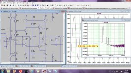
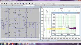
I have idea to make SMD type PCB for GainWire mk2. I choose bjts from ROHM as they have a transistors pairs in one case in different combination. I tried to simulate first by changing transistor pairs in the V/A converter part(Q11, Q12, Q3, Q4) from BC550C/BC560C to EMZ2 from ROHM. Simulation showed tenfold increase in THD, from 0.000007% to 0.000083% for the same signal level. I would like if someone can explain what model parameter/parameters are reason for that. I tried to figure it out by myself and appreciate a help here.
Simulated IPS only with ideal OPS in CFA configuration.
Attached Cordell and Rohm models(from ROHM site).
Damir
Simulated IPS only with ideal OPS in CFA configuration.
Attached Cordell and Rohm models(from ROHM site).
Damir
Attachments
- Status
- Not open for further replies.
- Home
- Amplifiers
- Solid State
- No NFB line amp (GainWire mk2)