@hornsteff Yes, that is definitely doable if I can figure out how to model that. Not for this horn, but I will try for the next one. i could do a 180 degree roundover and if I am correct, only single side machining would be necessary. While thinking about it, I could actually make some test prints to verify the idea even on this horn.
Is it so difficult to model a Tractrix-curve? Only 2D not 3D
I did many years ago calculate a tractrix-curve in excel and then export the x- y-data to auto-CAD and then i could print the curve out on a large plotter. It vase as a tool to make a big lathe. Never finished it though! But I did make some templates.
I think there is a tractrix calculater here: https://volvotreter.de/dl-section/tools/
Have to go now to HiFi-show in Hamburg.
Steffen
I did many years ago calculate a tractrix-curve in excel and then export the x- y-data
These days it can now also be done using Hornresp...
Attachments
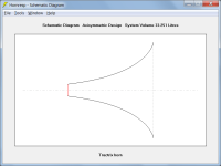

It is not difficult to model it, but to fit it to the nine sided horn. It took me yesterday an hour to figure it out with a half circle. Hornresp would be definitely the tool to generate the tractrix curve, I have used it for exponential multicell calculations.
However I am not sure I want tractrix - it is one of the candidates, but I strongly consider using @mabat 's equations to generate the roundover - if I can force then to make just the roundover with exit angle of the horn.
Another curve could be a logarithmic spiral. I need to compare them which would look the best and would fit the CNV since I think any roundover will do better than a basic half circle.
This is how it woud look like with a half circle roundover. Not bad, but a "flatter" curve would allow the roundover to be larger. The machined part would be wider with the same maximal thickness.


This is just a quick example of a flatter curve allowing 150 mm width vs 100 mm width of the half circle:

I need to play a bit more with the sliders to get some meanigful shape - generating the curve for the given size constraints is so easy with this.
I need to play a bit more with the sliders to get some meanigful shape - generating the curve for the given size constraints is so easy with this.
I tried to measure the angles of each corner to see how consistent they are. Any inaccuracy would make adding the roundover more difficult. I used a digital angle ruler and the tolerance was easily below 1 degree smallest to largest, maybe even less if measured properly. My right angles are usually on the same level of precision or even worse🙂
Hi Jaroslav
I think, that the thicker your petals are the more accurately they will align when assembled, if your CNC routes accurate angels on the sides of the petals.
You could maybe route a groove on the back-side of the petal where it is thickest, like behind the round-over to place a wire or something to pull the petals together while gluing!? You will maybe need to use some dowels to join the pieces? Making it more precise.
I have a cheap Flat-dowel-cutter to make alignment more precise when gluing, we call the dowels: Fish-dowels here in Denmark, works very well.
I do have another idea for alignment without dowels. Ask for it and I will try to make a wooden model and post a picture. Can´t explain in words.
Steffen
I tried to measure the angles of each corner to see how consistent they are
I think, that the thicker your petals are the more accurately they will align when assembled, if your CNC routes accurate angels on the sides of the petals.
You could maybe route a groove on the back-side of the petal where it is thickest, like behind the round-over to place a wire or something to pull the petals together while gluing!? You will maybe need to use some dowels to join the pieces? Making it more precise.
I have a cheap Flat-dowel-cutter to make alignment more precise when gluing, we call the dowels: Fish-dowels here in Denmark, works very well.
I do have another idea for alignment without dowels. Ask for it and I will try to make a wooden model and post a picture. Can´t explain in words.
Steffen
The tape method worked pretty well for me - but with the roundover, it would be difficult to use the same method I think - so it might be better to actually glue one piece at a time and that requires extreme precision since the errors add up and I could end up with a gap at the last seam.
I think I could drill dowel holes using a 3D printed jig for consistency and use precisely cut angle fixtures for holding two panels together.
I think I could drill dowel holes using a 3D printed jig for consistency and use precisely cut angle fixtures for holding two panels together.
I am also thinking about using multiple smaller holes instead of a single large one. What would be a good diameter to start? I can do 4 mm diameter or more.
I am also thinking about using multiple smaller holes instead of a single large one. What would be a good diameter to start?
I don´t follow? What holes do you mean? Port-holes?
Mark100 did some experiments with perforated metal-sheat over on the Klipsch-comunity years back. Maybe you can ask him for his experience?
Hi again.
I have been down in the basement to make a little mock-up, like a joint between two petals, to show my idea to glue together the nine petals and align them at the same time. I would call it the "finger-method".
The wooden "fingers" are temporarily nailed to the backside of the petals (MDF) so that they "interlock", aligning the petals. You have to be a bit precise with positioning the fingers, meaning with the same fixed distance from the throat on all petals. Depending on the size/length of your petals you can make three or four sets of fingers or even more. After gluing the fingers will be removed again.


The qiuck-gripp-spanner is just used to hold those two pieces together while making the photo.

I have shown a blue nylon-strap on the pictures to indicate a way to strap the nine petals together when gluing the whole lot together, using the fingers to hold the strap in place.
I hope the pictures are somehow self-explainatory.
I think with this "finger-method" you dont need to drill dowels!
Steffen
I have been down in the basement to make a little mock-up, like a joint between two petals, to show my idea to glue together the nine petals and align them at the same time. I would call it the "finger-method".
The wooden "fingers" are temporarily nailed to the backside of the petals (MDF) so that they "interlock", aligning the petals. You have to be a bit precise with positioning the fingers, meaning with the same fixed distance from the throat on all petals. Depending on the size/length of your petals you can make three or four sets of fingers or even more. After gluing the fingers will be removed again.
The qiuck-gripp-spanner is just used to hold those two pieces together while making the photo.
I have shown a blue nylon-strap on the pictures to indicate a way to strap the nine petals together when gluing the whole lot together, using the fingers to hold the strap in place.
I hope the pictures are somehow self-explainatory.
I think with this "finger-method" you dont need to drill dowels!
Steffen
Last edited:
A great idea, I will definitely try that. With some positioning jig, it should be easily done consistent. Yes, for holes I meant the port holes. Not sure if that is worth the effort and I like to see the port holes whole🙂
Here are some measurement from today, in room, no gating, just Psy smoothing. I used Open Sound Meter for real time response tuning with the DSP. I am pretty sure I do not have it optimal yet, but it is better than before. I also quickly tuned the green horn to match in SPL and delay and I am now enjoying the results. Loud and clear🙂
This is on axis:

This is off axis, ca 35 degrees, the microphone could still "see" the throat:

And the comparison shows the slightly problematic areas:

All in all, I am happy with it. And there is a potential to do it still better.
The most problematic part is the LF - here is the raw response:

That 800 Hz peak is unwanted, since the crossover frequency is now around 270 Hz between MF and LF. It toolk some effort to EQ it out.
Here are some measurement from today, in room, no gating, just Psy smoothing. I used Open Sound Meter for real time response tuning with the DSP. I am pretty sure I do not have it optimal yet, but it is better than before. I also quickly tuned the green horn to match in SPL and delay and I am now enjoying the results. Loud and clear🙂
This is on axis:
This is off axis, ca 35 degrees, the microphone could still "see" the throat:
And the comparison shows the slightly problematic areas:
All in all, I am happy with it. And there is a potential to do it still better.
The most problematic part is the LF - here is the raw response:
That 800 Hz peak is unwanted, since the crossover frequency is now around 270 Hz between MF and LF. It toolk some effort to EQ it out.
I have two small fullrangers with 1.4" throat adapter (not an ideal one, but it OK for the test). It is the Visaton FRS-5X and Sica 2H0,8SL https://sica.it/wp-content/uploads/2021/02/Z000795.pdf. I also have a custom faceplate for the R2604 ring radiator. All these will be tested on this horn to find out if they work better than the compression driver.
Attachments
I have noticed some strange shape of the LF impulse response:

The thick line is the LF, the thin line whole speaker. I wonder if that is due to back wave reflection, some LF speakers not wired in phase (will need to doublecheck that) or anything else. Strangely enough, the resulting impulse of the whole speaker with crossover and DSP looks really reasonable - but definitely, the phase is weird (not shown). The double peak confused the Open Sound Meter delay estimation.
I will have to investigate this further.
Edit: LF polarities checked and OK with a 1.5 V AA battery.
Last edited:
Pelanj, as far as I am aware, most programs need a high frequency cue ( above 5 khz ) for estimating the IR start time, so measuring the LF or MR by themselves would show a strange looking impulse, whereby measuring all sections at once will not.
There is quite a lot of HF energy evenin the LF - see post #93. The IR shape is really strange, I need to find out why.
How could I have missed this great post? https://www.diyaudio.com/community/...overs-room-correction-etc.349818/post-7213813
I did experiment a bit with the quick and dirty (and bad, room influenced) measurements just to see what is possible following roughly the tutorial using only REW track arithmetic and generated filters.

There are issues due to the measurements being incorrect, but this will really work!
I did experiment a bit with the quick and dirty (and bad, room influenced) measurements just to see what is possible following roughly the tutorial using only REW track arithmetic and generated filters.
There are issues due to the measurements being incorrect, but this will really work!
The same measurements, but this time using the TF function from VituixCAD generating 8th order linear phase LR crossovers. I am pretty sure that with proper measurement, this will be really good.

The leftover dips and phase rotations come most probably from reflections in the measurement, there might be also some misalignment in delays. The HF roll off was added intentionally.
The leftover dips and phase rotations come most probably from reflections in the measurement, there might be also some misalignment in delays. The HF roll off was added intentionally.
- Home
- Loudspeakers
- Multi-Way
- Nine-sided conical horn MEH