
Agree, Marvelous thread so far.
Interesting to see. Diy has challenges.
Seem to be moving past them quickly.
Interesting to see. Diy has challenges.
Seem to be moving past them quickly.
Hi Pelanj
It is looking really good! If only I was as fast as you.
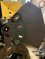
It looks like you have fitted the spacers for the midranges directly on the 16 mm chipboard. Does that mean, that you have something like 16 to 17 mm long portholes? I always thought that the portholes should be as short as possible, one of the reasons to use frostrums? Just curious.
What are the distances of your ports from the throat along the hornwall?
Steffen
It is looking really good! If only I was as fast as you.
It looks like you have fitted the spacers for the midranges directly on the 16 mm chipboard. Does that mean, that you have something like 16 to 17 mm long portholes? I always thought that the portholes should be as short as possible, one of the reasons to use frostrums? Just curious.
What are the distances of your ports from the throat along the hornwall?
Steffen
Thanks! A CNC and 3D printers make it easier. The port holes are 18 mm in total. I measured frustumized hole compared to a normal hole on the test print with no real difference. 25 mm diameter hole for the 3FE22 worked fine so far on 16 mm chipboard and 18 mm plywood/mdf - and it is easy to drill.
The mid holes are 9.6 cm from and the low holes are 33.5 cm from the throat along the horn wall (centers). The test print had the same distance for the mid hole and the response was reasonably close to what Hornresp predicted.
The mid holes are 9.6 cm from and the low holes are 33.5 cm from the throat along the horn wall (centers). The test print had the same distance for the mid hole and the response was reasonably close to what Hornresp predicted.

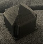
I designed a small back cover for the 3FE22. It will most probably not be used on the prototype, since there is no easy way to build a large enough box for the woofers.
I have an idea for the final design - it will be 8 sided, maybe with more sensitive mid drivers and two 12" for lows. The eight sided construction would allow for painting in a maltese cross inside - so that it could bear the name "MalteSyn". By the way, the prototype work name is 9Syn🙂
I have an idea for the final design - it will be 8 sided, maybe with more sensitive mid drivers and two 12" for lows. The eight sided construction would allow for painting in a maltese cross inside - so that it could bear the name "MalteSyn". By the way, the prototype work name is 9Syn🙂
Attachments
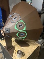
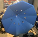
Very much enjoying reading this thread, thank you for sharing your progress. Can I ask, how did you decide to create the surface geometry for this particular throat, i.e. from a round opening to a nine-sided one? Did you just try to create the smoothest transition possible?Adapter machined from a leftover piece of 18 mm beech laminated board. If all goes fine, tomorrow I will start cutting the panels.
The geometry is using OpenSCAD hull function - which morphs circle to the nonagon on the thickness of the adapter. No advanced math used on my side. The nonagon is circumscribed to a circle, so the nine sided part of the horn is slightly larger than a circular horn would be.
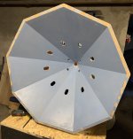
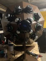
14 drivers are mounted on the horn. I hope to solder and crimp the wires tomorrow. I need to draw and print a holder for two Speakon connectors and dismantle the yellow prototype MEH to make some space for this one.
It is now pretty heavy, but still manageable.
It is now pretty heavy, but still manageable.
Attachments
Hi pelanj
I am following your thread with great joy 😀. Awesome.
When I look at your picture from the back of the horn (with all drivers mounted) it seems to me it would be possible to make an enclosure like a nine-sided "tube" with a bottom-plate. I would guess it still will be hidden from the front sight. This should not be too difficult to CNC and make for you. Just a thought 🙄
Regards
Steffen
I am following your thread with great joy 😀. Awesome.
I am considering 8 sided construction with more standard 2x12" on the sides - which would allow for a rectangular enclosure hidden from the front sight
When I look at your picture from the back of the horn (with all drivers mounted) it seems to me it would be possible to make an enclosure like a nine-sided "tube" with a bottom-plate. I would guess it still will be hidden from the front sight. This should not be too difficult to CNC and make for you. Just a thought 🙄
Regards
Steffen
This would be possible if there was no stand. And even then, the volume would be to low for these cheap woofers. The open back seems to work quite well for me. For the next version, I will need to figure out also back enclosure options and use better driver - not really soundwise,these are OK - but some allowing reasonable box volumes.
use better driver - not really soundwise,these are OK - but some allowing reasonable box volumes.
Very interesting topic. I have been wondering what T/S parameters would be best. The MEH that I am working on is going into a corner and will have a fixed internal volume. I will start to use some 25 year old Visaton 15" woofers, but I have designed my MEH so that I can upgrade to four Woofers per MEH, one in each "corner".
For instance I have been looking at the Faital Pro 12PR320 and 10P320 (16 ohm version for parallel-connection). They have the same "motor" but different different T/S-parameters.
So, although having a higher Fs the 10PR320 has a lower Vas then the 12PR320. I have been wondering if the 10PR320 would actually have a lower Fb compared to the 12PR320 for the same internal volume!? So what would be the best choice for domestic use?
Steffen
In general, I find the Hornresp simulations pretty close to reality - so I set up a model of the MEH to match the design as close as possible, set the voltage on the HF section to minimum to ignore it and then have several ME1 and ME2 records comparing the responses. The MEH wizard is a really powerful tool once you get used to it. I also have a separate .dat file for each design. Depending on the LF cutoff and SPL need, a pair of 10" should be more than enough - like in the SynTripP by weltersys. My smallest "Kallax" two way MEH is using a single Fane Sovereign 8 and can easily do over 115 dB at 2.5 meters down to around 140 Hz, which is already painfully loud in my small home office.
- Home
- Loudspeakers
- Multi-Way
- Nine-sided conical horn MEH