Well. now I am at it...... 😀
Came to look at the BMS 4526HE! It sells from TLHP for 92 €
https://en.toutlehautparleur.com/compression-driver-bms-4526he-8-ohm-0-63-inch-exit.html
https://www.bmsspeakers.com/index.php-49.html?id=4526he00
It might work well with your 3" midranges and have a good dispersion far up in frequency!?
I will stop here and go back to vacuum-cleaning 😳
Came to look at the BMS 4526HE! It sells from TLHP for 92 €
https://en.toutlehautparleur.com/compression-driver-bms-4526he-8-ohm-0-63-inch-exit.html
https://www.bmsspeakers.com/index.php-49.html?id=4526he00
0.63" NEODYMIUM HIGH FREQUENCY COMPRESSION DRIVER
FEATURES:
- Unique patented design
- additional shorting rings to reduce distortion
- High energy neodymium magnet assembly
- Annular ring diaphragm
- 113 dB sensitivity 1 W / 1 m
- Frequency range 1200 Hz to 30 kHz
- Ultra low distortion
- Ultra light weight and small size
- 1" (25.4 mm) Voice Coil
- 8 or 16 Ohms
It might work well with your 3" midranges and have a good dispersion far up in frequency!?
I will stop here and go back to vacuum-cleaning 😳

this could be simmed in abec but it would be a lot of work to construct the model from "nodes" like I've been doing in my open baffle modelling thread.Just for fun, I tried to simulate an open baffle with the radius of the horn depth . That comes in yellow. The green line is compound offset horn to simulate open back bass on the MEH and the blue one is MEH with a very large back chamber. All with 9 3S3P connected woofers. I do not know if compound offset horn (with a very short "back" horn) is the correct way of simulating the low section of a MEH with an open back, but it seems pretty legit to me. If I get something like the green curve, I will need around 8 dB boost to match the blue curve. The woofers can take 540 W compared to 40 W for a pair of 3FE22s (AES, peak is double the values). So there is plenty of headroom.
View attachment 1258893
If my simulation is correct, it would imply that running the mids with open back would not influence the respose by dipole cancellation in the pass band.
it wouldn't be so bad with a 4-sided horn and just two drivers.
One thing I've noticed from those sims, is dipole cancellation depends on radiation actually reaching the back, or at least the baffle edge, to be cancelled. Thus, it doesn't get there to be cancelled much above where the horn is losing pattern control, which is where you want it. Your green curve looks pretty reasonable to me as well. It "should" work to extend the directivity control lower, but it might result in a colored response because only a portion of the spectrum is dipole.
I am running my current rectangular MEH prototypes with open back mids and lows. Since they use a planar tweeter, they have an option to radiate the HF to the back as well. I slightly prefer closed back HF, with open back it was already a bit too much of ambience, most probably due to lack of space behind them. I might try an adjustable back firing tweeter once the prototype is built.
In the latest design, I plan to use 4 mids for higher SPL capacity - even on nine petals, they can be arranged almost in a square manner with just a small offset. Now the task is how to calculate the hole positions properly - I hope my trigonometry skills are good enough🙂
In the latest design, I plan to use 4 mids for higher SPL capacity - even on nine petals, they can be arranged almost in a square manner with just a small offset. Now the task is how to calculate the hole positions properly - I hope my trigonometry skills are good enough🙂
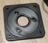
Another measurement with DE72 showed 1480 Hz notch - which is a bit lower than the Beyma. Looking down the throat, it seems to be also deeper and different (steeper) angle. The test setup works fine I would say. Now I am concerned about the low end of the mids. The "flare rate" rule predicts higher cutoff than Hornresp - but I trust Hornresp more than my calculations. In any case, mids down to 400 Hz should be easily doable.

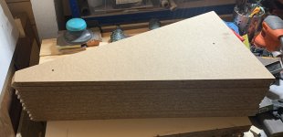
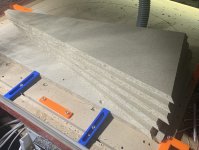
Five pieces machined, five more to go. The piece size is manageable, together, these will build a monster🙂 Serial production on the CNC is a piece of cake, so I started thinking about the next one having some sort of inner 3D profile. I am not sure if I will be able to create the the model, but at least a roundover and/or change of expansion to reduce diffraction and waistbanding should be doable.
Attachments
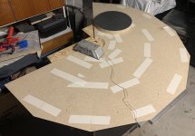
Some quick and dirty polar measurements of the printed test horn with blocked throat, open back mid and gated. The last three are out of coverage angle. Not too bad, the notch is at the same place as measured laid on a table. I am considering moving the mids a bit further away from the throat to move the notch to 1200 Hz for better loading on the mids. Any opinions on that?
I would like to implement a passive crossover between mids and HF to reduce the number of amplification channels. No low pass on the mids, just a notch filter on the peak above the notch.

I would like to implement a passive crossover between mids and HF to reduce the number of amplification channels. No low pass on the mids, just a notch filter on the peak above the notch.
First I would ask myself if that roll off on the low end is due to the horn's overall shape ( ie follows the radiation impedance curve) or due to the mid port's position on it. A simple HornResp model will tell you that. I have the vague opinion that moving the mid away 20%-30% further won't matter very much. I don't know where that opinion comes from. Probably from HR simulations I did long ago. I remember thinking that that effect while real was exaggerated for the benefit of the patent application. OTOH, at this point it's easy to try and so why not try it. There may well be some benefit or some unanticipated side effect.
BTW: I just have to say that you are having entirely too much fun with your CNC! 🙂
BTW: I just have to say that you are having entirely too much fun with your CNC! 🙂
The low end roll off in this measurement is caused by the open back mids on a short 3D printed horn (shown above, only the first 13 cm did fit my printer). I forgot to mention that by moving a bit further I hope to reduce also the small peak before the notch to get a more gradual roll off at the high end.
Hornresp is indispensable, I will try to play with the model a bit. It is definitely a good thing to have the possibility to move the mids a bit further than opposite. I will post the results later -I remember seeing a "knee" in the low end roll off, which was roughly matching the "flare rate" rule (I remembered it wrong, it was a filter enabled). Fitting the LF drivers on the outside of the horn will dictate their lowest distance to the throat, it seems there is still a good margin there to overlap with the mids.
CNC and chipboard are lots of fun indeed🙂
Hornresp is indispensable, I will try to play with the model a bit. It is definitely a good thing to have the possibility to move the mids a bit further than opposite. I will post the results later -
CNC and chipboard are lots of fun indeed🙂
Last edited:
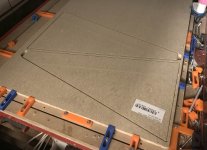
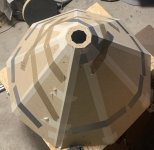
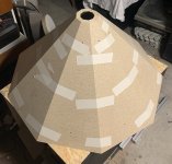
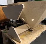
Dry fitting and glue up. I went out of gaffa tape, so I had to use what I had. For the real thing I need to have more tape and a larger table. It went quite well, but next time I need to pay more attention to the aligment. The throat is already glued on as well, I added 4 screws to make it stronger. One went through, so next time one of the corners needs to be drilled closer to the edge.
The size of the thing is impressive. Now I plan to test another front chamber/port types on the 3D printed horn.
The size of the thing is impressive. Now I plan to test another front chamber/port types on the 3D printed horn.
Attachments
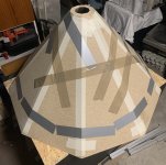
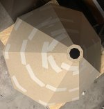
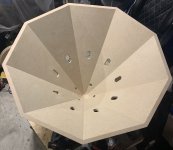
915 mm inner diameter is quite close to the edge of single man manipulation - and definitely the largest I can fit in this room🙂 When the placement of the drivers will be determined, this will get a simple stand with adjustable feet to be able to tilt it down a bit, the axis is getting a bit too high for seated listening.
Attachments

Holes drilled, I promised to myself to never do this again by hand🙂
I am curious about how the nine woofers will work. For the final pair, I am considering 8 sided construction with more standard 2x12" on the sides - which would allow for a rectangular enclosure hidden from the front sight, doubling as a stand for the horn.
I am curious about how the nine woofers will work. For the final pair, I am considering 8 sided construction with more standard 2x12" on the sides - which would allow for a rectangular enclosure hidden from the front sight, doubling as a stand for the horn.
Attachments

Awesome pelanj...you are leading the charge into new territory !
Can't' wait to hear how you think it sounds, and see how it measures...
Can't' wait to hear how you think it sounds, and see how it measures...
Holes drilled, I promised to myself to never do this again by hand🙂
I am curious about how the nine woofers will work. For the final pair, I am considering 8 sided construction with more standard 2x12" on the sides - which would allow for a rectangular enclosure hidden from the front sight, doubling as a stand for the horn.
That's a lot of holes. Do you plan to use as many (smaller) woofers? 🤔
- Home
- Loudspeakers
- Multi-Way
- Nine-sided conical horn MEH