So with the SDG signal generator switched on... and switched off.

I need to sort out the final hardware updates for this, that includes the power supplies, the external clock, and a few other modifications.
Fitting the lit on it seemed to really work some magic 😀

I need to sort out the final hardware updates for this, that includes the power supplies, the external clock, and a few other modifications.
Fitting the lit on it seemed to really work some magic 😀
So I've been cleaning up some of the physical internals.
I'm starting to see the need for some additional power filtering:

Also with a 10uF film cap (the device is to be AC only), the input seems to show quite a bit of noise from the signal generator, including a larger noise floor caused by the digital generation of the sine wave.

So I think the next steps are really to target the power supply/ground noise.
I'm starting to see the need for some additional power filtering:
Also with a 10uF film cap (the device is to be AC only), the input seems to show quite a bit of noise from the signal generator, including a larger noise floor caused by the digital generation of the sine wave.
So I think the next steps are really to target the power supply/ground noise.
I’ve ltspiced a set of LT3042 based supplies to target the 50Hz mains noise, my thinking is a shared 8V supply
Then a 2x22V supply using LT3080 to drop to +/-15Vdc for the ADC.
I need to check the thermals but this seems achievable.
- two 3042 supplies - one for the oscillator and one for the 3 fan out IC
- one 3042 for the adc 5V digital line
- one 3042 for the STM32 digital 5V although an option here is to use USB bus power instead (this works given the disco board is ~700mA maxed out) but then use i2s/i2c isolator.
Then a 2x22V supply using LT3080 to drop to +/-15Vdc for the ADC.
I need to check the thermals but this seems achievable.
Last edited:
IMO the steadily rising noise floor towards LF is more of an issue. What are you using as DAC in your measurements?
Regarding mains related noise some of that may be "environmental". Try moving the devices to another location in the room. LT3042 may not help against radiated noise.
Your ADC has quite adequate power supply already. LT3042 has lower LF noise than ADP7118 but PSRR is similar.
STM32 should work fine with USB power. I've never had to use anything else.
I'm currently using an SDG1032X to provide the 24.576MHz clock signal currently, I suspect that some of the noise is from that (my thinking that the noise affecting the clock and thus some of the LF ADC noise).
The ADC needs a power supply (currently it's using both my cheap bench SMPS so I'd like to get them back!). The ADC and the STM both sit within a hammond instrumentation case (solid metal) although the top needs secure grounding.
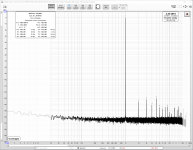
I just did a disconnected input (only connected for the master clock):

I don't think that's all 1/f noise either as it's too shallow. My gut feeling is that the SDG as a master clock is injecting phase noise so replacing that should help reduce noise. Same with better case grounding etc.
It may even be input noise playing with the antialiasing filter in the ADC. I'll investigate over this week. It could be the SMPS noise coming into the OPAs that's then causing 1/f noise increase but it seems very shallow compared to any of the images I've seen of that.
The ADC needs a power supply (currently it's using both my cheap bench SMPS so I'd like to get them back!). The ADC and the STM both sit within a hammond instrumentation case (solid metal) although the top needs secure grounding.
I just did a disconnected input (only connected for the master clock):
I don't think that's all 1/f noise either as it's too shallow. My gut feeling is that the SDG as a master clock is injecting phase noise so replacing that should help reduce noise. Same with better case grounding etc.
It may even be input noise playing with the antialiasing filter in the ADC. I'll investigate over this week. It could be the SMPS noise coming into the OPAs that's then causing 1/f noise increase but it seems very shallow compared to any of the images I've seen of that.
Last edited:
SDG1032X may well be the cause of rising noise floor towards LF.
Just as a comparison here is a loopback measurement of my DAC/ADC/STM32F7 combo. DAC (AK4493) & ADC (ES9822PRO) mains powered, STM32 USB powered. All boards naked in front of my LCD screen.
Just as a comparison here is a loopback measurement of my DAC/ADC/STM32F7 combo. DAC (AK4493) & ADC (ES9822PRO) mains powered, STM32 USB powered. All boards naked in front of my LCD screen.
Attachments

SDG1032X may well be the cause of rising noise floor towards LF.
Just as a comparison here is a loopback measurement of my DAC/ADC/STM32F7 combo. DAC (AK4493) & ADC (ES9822PRO) mains powered, STM32 USB powered. All boards naked in front of my LCD screen.
Are you running a dual-mono ADC configuration?
I think the 8922 probably has the edge on the 5572 but it will be interesting to see once it's some of these issues are resolved.
Not in this case, but my ADC board can be switched to mono-mode. Mono-mode does have some drawbacks. It lowers noise but loopback THD may improve or worsen depending on the matching of ADC channels.
So I've designed myself a master clock with a fanout for driving up to 3 50ohm devices and I've ordered those plus some additional voltage regulators (ouch!). 99% of the components are SMT. These should be with me next week. So let the fun begin!
https://www.ieee.li/pdf/viewgraphs/jitter_basics_advanced.pdf
So this seems to indicate periodic jitter possibly caused by interference.
Also the 1KHz signal shows quite a large phase noise (the wide base) and so I suspect the effect on measurements then increases the noise floor. If that level of noise is present on the 1Khz signal, i suspect that the same is true for the 24.567Mhz with the same wide base and high noise floor.
I have ordered a Crytek CCHD which is i know isn’t super low phase noise but it will be a good learning experience and a good starting point.
So these are going to be interesting to solder.. I have some 0402 caps which are the thickness of those legs. Challenge accepted!

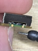
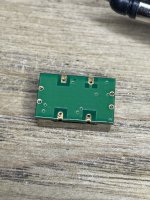
Hm. I think I may have bust my CCHD-957. After checking the supply (3.3 ±0.3V) and pin outs I thought it would be safe to have a quick test ahead of the weekend session to attempt to make the circuit board.
I applied 3.30V from the SMPS power supply (I also hooked the Brymen to the probes and it shows it's only ±0.06V) and put a probe on from the scope and the signal appeared 🙂 I compared against the SDG1032X. The important point here is that the scope can't really test this level of phase noise but it can show noise on the waveform. It appears the CCHD has less noise than the SDG1032X.
However now it seems to only output a floating DC voltage. I tried shorting over to E/D pin to trigger output but nothing it simply sits high.
Incidentally the inside (looking through the gaps) seems to have a ceramic crystal compared to the old 957 that appeared to have a separate crystal enclosed in it's own metal can.
The only thing I can think of is that it needs some current limiting.. which seems daft to some noise caused a transient. I assume that it's an amp inside the oscillator that decided to die hence providing a semi short. There's no power draw on the meter and connecting the E/D pin to Vcc doesn't seem to enable output.
A little soul destroying but that's beginners "luck". A learning experience.
Attachments
Last edited:
The Crystek CCHD-957 load is 15pF .. the scope is 1Mohm but 15pF so I'm wondering if that load has killed the output of the oscillator. This is interesting though as my design has a TI CDCLVC1103PW clock buffer but it doesn't give the input capacitance which would be the load (only the output). A different Renesas buffer gives a input capacitance as 3pF for example.
I think I will need to lick my wounds and look at changing the design with more modern buffer chip as the TI doesn't specify the input capacitance and it doesn't appear on the web!
I think I will need to lick my wounds and look at changing the design with more modern buffer chip as the TI doesn't specify the input capacitance and it doesn't appear on the web!
Thank you I'll have a look at that.You could use LMK1C1103 instead. Cheaper, better performance, same pinout, input capacitance 7pF.
I've double checked the clock-to-ADC board connection too. It's a 15cm SMB-SMB RG-316 (95.01pF/meter), so that below 1pF in the connection.
Just found a really nice low phase noise OXCO from RTX, it shows -130dB at 10Hz. https://rfx.co.uk/uploads/Model-Data-Sheets/OS936-10A.pdf both probably well outside my price range and also the minimum order is likely to be more than 1.. but interesting anyway. RTX incorporated laptech.
There may be some good options to replace the CCHD but in a simple, easy to purchase package with ~-100dB lowest frequency noise it's a good compromise for a starting point.
There may be some good options to replace the CCHD but in a simple, easy to purchase package with ~-100dB lowest frequency noise it's a good compromise for a starting point.
Digikey has RFX's oscillators suitable for digital audio. Quite expensive indeed.
https://www.digikey.fi/en/products/detail/rfx-limited/OS560-2465-022/16395338
https://www.digikey.fi/en/products/detail/rfx-limited/OS560-2465-022/16395338
Doesn't that oscillator have an enable pin? I have used them in the past and they seem quite durable.
The ultra low phase noise oscillators are nice but way overkill if the path from the oscillator to the internal registers in the DAC chip is not also designed to that level. You need things like high revers attenuation buffers to prevent interactions, isolated power supplies or the supply noise will pass through to the oscillator. There is a really involved science to getting ultra low phase noise. And below some calculable number (144 dB for 24 bit) it won't make a difference. Digital operates in finite quantum steps. While that lower limit is quite low -150 dB phase noise is really significantly lower. And the best 24 bit system for audio is almost 20 real bits.
The ultra low phase noise oscillators are nice but way overkill if the path from the oscillator to the internal registers in the DAC chip is not also designed to that level. You need things like high revers attenuation buffers to prevent interactions, isolated power supplies or the supply noise will pass through to the oscillator. There is a really involved science to getting ultra low phase noise. And below some calculable number (144 dB for 24 bit) it won't make a difference. Digital operates in finite quantum steps. While that lower limit is quite low -150 dB phase noise is really significantly lower. And the best 24 bit system for audio is almost 20 real bits.
Doesn't that oscillator have an enable pin? I have used them in the past and they seem quite durable.
The ultra low phase noise oscillators are nice but way overkill if the path from the oscillator to the internal registers in the DAC chip is not also designed to that level. You need things like high revers attenuation buffers to prevent interactions, isolated power supplies or the supply noise will pass through to the oscillator. There is a really involved science to getting ultra low phase noise. And below some calculable number (144 dB for 24 bit) it won't make a difference. Digital operates in finite quantum steps. While that lower limit is quite low -150 dB phase noise is really significantly lower. And the best 24 bit system for audio is almost 20 real bits.
It does have an enable pin - disabling results in DC of about 0V and enabling results in just a DC offset of 2.37V on a 3.3V supply but no oscillation (using the scope). I really think it's an ex-oscilator unfortunately.
For me if I can get a separate clock that is moderately quiet for the ADC to provide 120-130dBV that will do for me.
- Home
- Design & Build
- Equipment & Tools
- Nick's audio test system (AK5572 ADC 129KHz 32bit stereo balanced input)