Cartridge manufacturers are forced to make load recommendations based on cable capacity. With a typical capacitance of about 200 pF, the resonance shifts into the audio range, and 47 kΩ is needed to dampen it.I completely agree with Nikolai Sukhov - for a MM cartridge, the use of a load of 47 kohm is not always optimal.

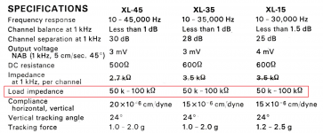
I have 2 turntables (70s and 80s of release). And both have a cable capacity of about 80 pf ( together with the capacity of the wires in the tonearm ) . I measured it . In addition , many cartridge manufacturers indicated the load range for their 47k - 100k cartridges . And I have such cartridges .Cartridge manufacturers are forced to make load recommendations based on cable capacity. With a typical capacitance of about 200 pF, the resonance shifts into the audio range, and 47 kΩ is needed to dampen it.
Attachments
Do you know how to make 25pF phono cable?
25pF is probably already in the arm.
What is the hint?
25pF is probably already in the arm.
What is the hint?
About 20-25pf in the arm . The signal cable of many Japanese turntables had a very small capacity - 60-70pf. I had several Japanese turntables - Sony, Hitachi, Pioneer, Kenwood , Onkio , and others - all of them had a cable with a small capacity ....A cable with a small capacity is easy to make yourself - for example , from a cable of the RG-59 type or similar. Also - there are many microphone cables with a capacity of 80- 100 pf per 1 meter length.Do you know how to make 25pF phono cable?
25pF is probably already in the arm.
What is the hint?
To be honest , you will not notice any advantages in sound from reducing the cable capacity from 80 to 25 pf by ear . A signal cable based on an antenna cable can have a capacity of about 30 pf per 1 meter - depending on the brand and diameter . I 've done these . But I didn 't notice any advantages in sound . If you really want to reduce the capacity of the cable , you can just reduce the length of the cable - only 0.6 meters is enough . This means that the cable capacity will also decrease .So it rather impossible to get 25pF without hard surgery?
There are only two ways to reduce the capacitance per unit length of a coaxial cable: using a dielectric with a small relative dielectric constant and using a large ratio of the inner radius of the shield to the ratio of the inner conductor. For example, a thick, polyethylene-foam-filled cable with a very thin inner conductor would have a low capacitance per unit length, a thin, PVC-filled cable with a thick inner conductor a high capacitance per unit length.
Increasing the load capacitance from 25 pF to 70 pF gives a peak in the frequency response of 5 dB and shifts it down in frequency. Of course, nothing will be noticeable by ear, few people hear above 16 kHz, but from a technical point of view, this is ugly. It is not possible to reduce the capacitance of the cable, except for exotic solutions with a twin shield and active capacitance compensation. It remains to place the RIAA preamplifier inside the turntable. This requires its disassembly, which is not acceptable to everyone. From this point of view the "Phaedrus PHLUX active phono cartridge" solution looks beautiful. It only requires a shell replacement. The printed circuit board can be made very light, the frequency of the main resonance of the tonearm will not change much.
Attachments
5 dB with or without iron losses?
You could make a negative input capacitance if you wanted to. Connect a capacitor with capacitance C between the input and the output of an ideal non-inverting amplifier with a frequency-independent voltage gain A > 1 and Miller effect will result in an input capacitance (1 - A) C < 0.
With a practical amplifier, you have to account for the input capacitance of the amplifier itself, of course. You will also have to think about ways to keep it stable at frequencies where the cable doesn't behave like a lumped capacitance anymore, and it may turn into an oscillator when the cable is made shorter.
Yes, without taking into account the loss in the iron. I took the primitive model schematic from post #89 just for comparison purposes. Obviously, it is possible to increase the input resistance, but this must be done in accordance with the input capacitance. If it increases (for example, due to the addition of a cable), then 150 kOhm can no longer be used. The cartridge manufacturer offers a simpler (but not the most optimal) option: always take 47 kOhm and add a capacitor at the input. So you can match the input for any reasonable cable capacity.5 dB with or without iron losses?
You could make a negative input capacitance if you wanted to.
I find it more productive to use a transimpedance amplifier with zero input impedance. This will eliminate the problem of cable capacitance, but another problem appears - the compensation of the LR constant of the cartridge. Moreover, this adjustment will affect the linearity of the frequency response in the middle of the audio range, which is bad. In the classical case, the capacitance of the cable leads to non-linearities near 20 kHz, where a human still does not hear anything.
Another aspect is that the classic LC-circuit input forms a 2nd order low-pass filter above 20 kHz. I find this useful. Vinyl has an output signal spectrum much wider than 20 kHz, but only distortion is contained there. You can verify this if you look at the spectrum of a test disk with a single-frequency signal recorded - the spectrum will still have a "tail" much higher than 20 kHz. If this is not cut off by the filter, the turntable will introduce ultrasonic noise further into the path, which can lead to intermodulation distortion.
I read that line of reasoning about signals above 20 kHz from more people here, but it seems illogical to me. With the same reasoning, I could also play back a test record with a 100 Hz sine wave on it, see distortion products at 200 Hz, 300 Hz and so on and conclude that everything from 200 Hz onwards is only distortion that can better be filtered off.
Unfortunately, we cannot filter everything above 200 Hz, since there may be a useful signal there. But there can be no useful signal above 20 kHz (this is beyond hearing), so it is desirable to filter this area.
Placing a head amp inside the turntable may be the only way to use 150k input impedance.
Using only tonearm wire
Then the RIAA amp uses 50 mV as the input and cable capacitance effect is eliminated.
Using only tonearm wire
Then the RIAA amp uses 50 mV as the input and cable capacitance effect is eliminated.
...with an unrealistic cartridge impedance model, the more realistic one is disconnected according to your schematic, and with no model at all for the mechanical response.Stepping parasitic Cin from 20 pF to 100 pF (at Rin 150 kOhm).
In the end I realize that people in their 70's might enjoy more highs anyway...so why not having such a response?!
The "realistic" model from this circuit gives strange results in the HF region, while this is not clear. Regarding mechanical resonance, the issue is debatable. We discussed this with Nick Sukhov, he is of the opinion that for most cartridges the influence of mechanical resonance is insignificant and it is enough to make the "electrical" frequency response flat. In any case, this is the second step. By adjusting R12, it is possible to compensate for the effect of mechanical resonance, but this can only be done with a reliable test disk.
Attachments
I see. The problem is that I only modelled the impedance, not the impact of the parasitics on the Thévenin voltage (open terminal voltage). I made the model to check some noise optimization calculations, not the transfer with unusual load impedances. Chances are that the capacitances cause a roll-off of the Thévenin voltage as well as a reduction of the impedance, but only the second effect is in the model.
If the EMF source is connected in series with this model, then the result is logical - at high frequencies, the impedance decreases due to shunt capacitors, therefore, the signal increases. In reality, the EMF sources are coils, if an external source is connected in series with the coil, everything becomes normal at high frequencies. The overall frequency response when changing the input capacitance from 20 to 100 pF has a drop of -0.8 ... -2.5 dB at 20 kHz. If you try to increase the "aperiodic correction" resistor R12 to 10 kOhm, the frequency response deviations are +/- 1 dB at 20 kHz. All this with a 150 kΩ input resistor. It looks optimistic, this phono stage can also be used with an interconnect cable. If, of course, the cartridge model is correct.
Addendum: this model with the recommended load of 47 kΩ + 400...500 pF gives very poor results, -6...-7 dB roll-off at 20 kHz.
Addendum: this model with the recommended load of 47 kΩ + 400...500 pF gives very poor results, -6...-7 dB roll-off at 20 kHz.
Attachments
Last edited:
Yes, putting it in series with the inductances makes sense.
Regarding the roll-off with the recommended load: that's why I expect this cartridge to have a strong mechanical resonance, otherwise it would not make sense that the manufacturer recommends such a high load capacitance.
Regarding the roll-off with the recommended load: that's why I expect this cartridge to have a strong mechanical resonance, otherwise it would not make sense that the manufacturer recommends such a high load capacitance.
- Home
- Vendor's Bazaar
- Nick Sukhov SU-XXI MM Phono stage -85 dBA SN ratio...