Some days you can't do anything right. The formula for the Q is on page 411 of the Radiotron Designers Handbook and the Q is actually 1.05. I claim that you need a Q of about 0.6. You know that if the Q is 0.5 you don't have any electrical overshoot and ringing. However, it will take forever (literally) to reach steady state. If the Q is over 0.707 you will have peaking. Half way between is about 0.6. I am confused by the following statement.
" you must keep in mind the fact that cartridge has frequency dependent effective series resistance much more than ohmic DC resistance."
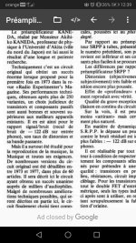
I have two attachments that show you why. These network analyzer graphs are on reactance frequency paper so you can read the values right off the graph. They are about 50 years old. We were trying to find the best electrolytic capacitors. As you can see this manufacturer was a little optimistic when he advertised this capacitor as 2,200 mfg. It barely makes 2,000 mFd. You can plainly see at resonance the ESL and ESR. The next graph is one winding of an open circuited transformer. You can plainly see the Equivalent Parallel resistance and capacitance. Inductors have an Equivalent Parallel Resistance. Can you tell me where you get this series resistance?
" you must keep in mind the fact that cartridge has frequency dependent effective series resistance much more than ohmic DC resistance."
I have two attachments that show you why. These network analyzer graphs are on reactance frequency paper so you can read the values right off the graph. They are about 50 years old. We were trying to find the best electrolytic capacitors. As you can see this manufacturer was a little optimistic when he advertised this capacitor as 2,200 mfg. It barely makes 2,000 mFd. You can plainly see at resonance the ESL and ESR. The next graph is one winding of an open circuited transformer. You can plainly see the Equivalent Parallel resistance and capacitance. Inductors have an Equivalent Parallel Resistance. Can you tell me where you get this series resistance?
Attachments
You can convert one into the other for a given frequency, R = G/(B2 + G2). It's just a mathematical trick.
I once tried to model the impedance of a Shure V15-III with frequency-independent resistances, inductances and capacitances and didn't get very far with just one series and just one shunt resistance. Instead I had to split up the inductance and give each part its own parallel resistance.
Anyway, the point is that the losses of a cartridge are greater than you would expect based on its DC resistance, which helps to damp the resonance with the load capacitance.
Last edited:

Yes it is better but try to emulate with some different reactive models and off-course not forget to add reactive factors from connecting cable inside the arm - connectors - interconnect cables and finaly connectors and cables inside the unit if they are bit longer?As promised a measurement of a cartridge using a VNA done by Hans Polak working with Gpapag. Interesting part is that electrically its less than 0.5dB down at 20kHz with 150pF||47k. No need for any mechanical pick me up from the stylus, and none visible in a frequency sweep with a credible test source.
.
I am using 68K (minimum) first R to ground @ input MM Phono, without any C paralleled. Dynamic capacitance of input high-mju stage is enough... (But i restrict my self to JFET SE or Tube Single ended input...)
I certainly don't see it happen with tubes as 0.5pF x 100 gain(ecc83) makes 50pF, while input j-fets gain is inexistent (<1) in cascodes and barely noticeable if at all inside a closed feedback loop ... Marcel had an interesting study on why there's basically no Miller capacitance in the first stage due to feedback where he basically dismissed any cascode utility for avoiding Miller effect.Unless the first stage has about 5... 10 paralleled 2sk170 jfets on the input there's no significant capacitance loading.I am using 68K (minimum) first R to ground @ input MM Phono, without any C paralleled. Dynamic capacitance of input high-mju stage is enough... (But i restrict my self to JFET SE or Tube Single ended input...)
They can be found at this long thread (rare but one of the times that members cooperation on technical issues runs smoothly and productively) 🙂Cool. Are their models being publicly archived somewhere by chance?
https://www.diyaudio.com/community/threads/mechanical-resonance-in-mms.303389/post-4978912
George
I looked in an old book of mine and found that you can convert a resistor in parallel with an inductor into a resistor in series with the inductor using the formula Rs*Rp=L/C. The product is a constant.
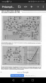
The riaa eq is different but the amp schematic is totally the Kenwood from 1981.
The 150k will raise the top end
The 150k will raise the top end
it is almost the same as opamp virtual groudMarcel had an interesting study on why there's basically no Miller capacitance in the first stage due to feedback
Can you show us your model? This is very interesting, especially from the point of view of the real quality factor at a frequency of 15-20-25 kHz (a decade ago I have measured Q of Shure M44 @ 20 kHz and AFAIR it was less than 0.5)I once tried to model the impedance of a Shure V15-III with frequency-independent resistances, inductances and capacitances and didn't get very far with just one series and just one shunt resistance. Instead I had to split up the inductance and give each part its own parallel resistance
Here it is. Don't ask me about the physical meaning of the components, I've just been tweaking the circuit until it came close to Richard Visée's Shure V15-III impedance measurements.

By the way, you can see in table 2 of my October 2003 article that the shunt conductance G is about 14.5 uS to 12 uS between 10 kHz and 20 kHz, so that's equivalent to a parallel resistance of on average about 75 kohm that represents both the copper and the iron losses between 10 kHz and 20 kHz. It's calculated straight from the magnitude and phase measured by Richard, without the inaccuracies of trying to manually fit it to a lumped model.
By the way, you can see in table 2 of my October 2003 article that the shunt conductance G is about 14.5 uS to 12 uS between 10 kHz and 20 kHz, so that's equivalent to a parallel resistance of on average about 75 kohm that represents both the copper and the iron losses between 10 kHz and 20 kHz. It's calculated straight from the magnitude and phase measured by Richard, without the inaccuracies of trying to manually fit it to a lumped model.
Last edited:
a parallel resistance of on average about 75 kohm that represents both the copper and the iron losses between 10 kHz and 20 kHz. It's calculated straight from the magnitude and phase measured by Richard, without the inaccuracies of trying to manually fit it to a lumped model.
It roughly corresponds to my measurements, when the BM560 Q-meter for the Shure M44 cartridge showed a quality factor lower 0.5, although it measured at a frequency of 50 kHz (this is its lower limit of the measurement frequency). One thing I must say - MM cartridge @ audio HF 10-20 kHz has equivalent series resistance at least 10 times more than @ DC and Q is less than 1. And using of electrical damping of mechanical resonance is an unsuccessful method (I do not need 24 dB\oct LPF). It is better to just throw outdated cartridges with an overly massive "lead" 😉 cantilever more than 0.5 mg in the trash and use modern boron\beryllium ones with effective tip mass of 0.25-0.4 mg or lower without mechanical problems @ 20 kHz and lower.
Last edited:
[skip]I am confused by the following statement.
" you must keep in mind the fact that cartridge has frequency dependent effective series resistance much more than ohmic DC resistance."
See fig. 8-46 and use formula (8.76) at attached fileInductors have an Equivalent Parallel Resistance. Can you tell me where you get this series resistance?
Attachments

The circuit and formula both are internationalThank you. my Russian is a little rusty,🙂

Last edited:
Translation from russian [ https://www.patreon.com/posts/eshchio-odno-pro-70335881 ] :
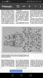
Greetings to all participants! I assembled a test version, please do not kick the connectors and ceramics in the correction - the assembly is a test one. I’m sitting and listening… the tweeters are amazing, even though I’m listening now with the most ordinary Ortofon OM-5 head, I’ve never heard such tweeters from her, although I had the opportunity to listen with various correctors, both industrial and self-made, including tube ones…
In general, it’s amazing to pour epithets about the sound, I don’t know how and I’m not going to, even in this form - the sound is crystal clear and the highs just blow their heads, while there are no problems with the bottom either, everything is plump (unlike those cases when some proofreaders are incredibly detailed, but as a rule, due to the missing bottom, so it's hard to listen to them)
In general, I sit and re-listen to a bunch of material again and, like a child, I rejoice 😉
The design is definitely worthy of attention!
I have been following Nikolai Evgenievich with interest since school, from the very beginning and the termination of publication I was a subscriber of his magazine, I still keep and re-read ... and in recent years, thanks to RadioHobby, I subscribe to AudioXpress - you know nostalgia)
So I want to say a huge thank you to Nikolai Evgenievich for his work and incredible circuit solutions!
PS: 120 the lighthouse is waiting for its time, I hope Nikolai will please us with something modern and for magnetic recording, because the reincarnation of his corrector is definitely a success!
Attachments

Isn't 150k too much? If the load resistor is smaller, the damping of the resonance is better, and the 1/f noise is lower. I would try 10k instead of the usual 47k.
Only for a single frequency. BTW which capacitor is C in the formula?I looked in an old book of mine and found that you can convert a resistor in parallel with an inductor into a resistor in series with the inductor using the formula Rs*Rp=L/C. The product is a constant.
Last edited:
L is the cartridge inductance and C is the load capacitor. This is the simple model that consists of an inductor, capacitor and resistor. The resistor can be in series with the inductor or in parallel with it. The book doesn't say anything about the formula being valid at only a single frequency .
I completely agree with Nikolai Sukhov - for a MM cartridge, the use of a load of 47 kohm is not always optimal. In the 70s , quite a lot of preamps with cartridge load settings were produced ( Victor , Nikko, Yamaha , Nakamichi and others ) . And usually the upper limit of resistance there was 100 kohm . For cartridges with an inductance of 700 or more mH , this mode is more optimal .... And if you remember carefully, many Shure, Ortofon, Empire (and many others) cartridges had an inductance of 700-800 mH windings..... I also use a load of more than 47 kohm (usually within 68k - 100k ) - my phono-preamps are equipped with such settings.
I am no expert in advanced electronics but love to learn new things. Actually i found this type of schematic described in the L' Audiophile nr.3/1978 under the name Kaneda. The concept was originally published in Radio Experimenters Magazine in 250 variants from 1973 to 1977 so way earlier than Keenwood or Kaneda. It has at least 60 articles from '73 to' 77 wich describes the functionning principles and judicious selection of the passive/active components. Its sound signature is very sensible to the PSU choice. Bellow are just a couple of example of this approach.The riaa eq is different but the amp schematic is totally the Kenwood from 1981.
The 150k will raise the top end
I am curious what are the differences between Kaneda and your version Mr Sukhov? How would you compare your variant? PSRR? Measurements and pairing and maybe sound? Did you tried the Kaneda? I am very curious in your response.
Would you be kind to describe abit the circuit and why you made it as it is, like in your book?
My experimentation with mm phonos on dust or cracks chapter is that the best are in this order: tubes, Ge (abit noisy), bipolars and the last are jfets.
How would you describe this type of mm preamplifier from this point of view, because lets face it, not all our discs are Philips Red Label or RCA red label or Columbia broadcast or 45s?
I also have old Melodia printings that have small cracks because of the age... Old recordings sound incredible but are susceptibile to this issue....
Thanks in advance.
Ps:
As i see it Kaneda is a very well known mm preamplifier and the man itself is still publishing in MJ Radio of Japan and is a very respected engineer and professor as you are Mr Sukhov. (for those who dont know)
The 2sk30agr is the same as 2sk208gr....
Attachments
- Home
- Vendor's Bazaar
- Nick Sukhov SU-XXI MM Phono stage -85 dBA SN ratio...