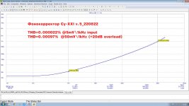
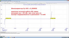
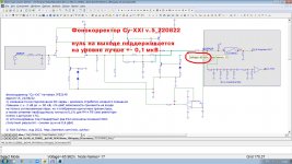
Phonopreamp Су-XXI v.5_220822: simplified requirements for components and slightly improved characteristics
https://www.patreon.com/posts/phonopreamp-su-v-70903013
https://www.patreon.com/posts/phonopreamp-su-v-70903013
Attachments
You can read detailed description here (in English):Would you be kind to describe abit the circuit and why you made it as it is, like in your book?
https://www.patreon.com/posts/mm-constant-loop-67857060
I made a small mistake. EMF should be distributed between the parts of the inductance in proportion not to the inductance, but to the number of turns (the square root of the inductance). But this does not lead to significant changes.Yes, putting it in series with the inductances makes sense.
I do not really believe in such a large impact of mechanical resonance. Rather, the model is not quite adequate. Real measurements required. This can be done by injecting a signal into the cartridge circuit by including a small resistor in the ground conductor. By selecting Rin, Cin, you can achieve a flat "electric" frequency response. According to the model, a flat frequency response is obtained at Rin = 220 kOhm, Cin = 75 pF. And then check the frequency response using a test record. Unfortunately, I don't have Shure V-15.I expect this cartridge to have a strong mechanical resonance, otherwise it would not make sense that the manufacturer recommends such a high load capacitance.
Attachments
Then you have the same issue as with your earlier simulation: completely flat Thevenin voltage.
What's the issue? Placing an EMF source in series with the cartridge does not give a large error in the audio range. A large increase in voltage is observed in the ultrasonic range.
OK, then that's no big deal.
I have no Shure V15-III either. Impedance measurements can be found here:
https://www.diyaudio.com/community/...ono-stage-85-dba-sn-ratio.387375/post-7054466
You can calculate the transfer from the Thevenin voltage to whatever load you like from that, it's just a complex voltage division.
I have no Shure V15-III either. Impedance measurements can be found here:
https://www.diyaudio.com/community/...ono-stage-85-dba-sn-ratio.387375/post-7054466
You can calculate the transfer from the Thevenin voltage to whatever load you like from that, it's just a complex voltage division.
I'm looking at a transimpedance amplifier. The goal is to make the amplifier insensitive to cable capacitance. Since it's a bad idea to build a phono amplifier inside a turntable, it requires disassembly. The graphics are beautiful. But another problem arises. With the classic matching of 47 kOhm + some capacitance, the nonlinearity of the frequency response is only at the top of the range, where the human ear does not hear anything. In the case of TIA, it is necessary to compensate for the parasitic pole tau=L/R, which is typically in the middle of the audio range. The inaccuracy of this compensation will be clearly noticeable by ear. What is unexpected - for TIA, this single adjustment is enough to make a flat frequency response for both a primitive cartridge model with only L and R, and for a complex Shure V-15 model.You can calculate the transfer from the Thevenin voltage to whatever load you like from that, it's just a complex voltage division.
Attachments
"Placing a head amp inside the turntable may be the only way to use 150k input impedance.
Using only tonearm wire"
The Revox B291 turntable did exactly that. The preamp was in the plinth on the PC board,
Of course, the price was outrageous so they didn't sell many.
Using only tonearm wire"
The Revox B291 turntable did exactly that. The preamp was in the plinth on the PC board,
Of course, the price was outrageous so they didn't sell many.

I don't understand. I did the same thing in the 1970s. I had a Thoren's TD125 turntable, a Mayware Formula 4 tonearm on an SME plinth. I also had a Leach JFET preamp which I mounted under the turntable in the plinth. I had about a 2-inch connecting cable between the preamp and tone arm. Naturally, I soldered the output cable directly to the preamp so I had an output cable with RCA plugs.
What do you mean by the Cin of a transimpedance amplifier? A transimpedance amplifier ideally has a zero input impedance.What is unexpected - for TIA, this single adjustment is enough to make a flat frequency response for both a primitive cartridge model with only L and R, and for a complex Shure V-15 model.
Basically the capacity of the interconnect cable. And other parasitic capacitances. In order for the TIA not to show an increase in noise gain at high frequencies, it will be necessary to add neutralization circuits for this capacitance.What do you mean by the Cin of a transimpedance amplifier? A transimpedance amplifier ideally has a zero input impedance.
So what you see in post #147 is due to imperfections of the transimpedance amplifier (probably mainly finite loop gain) causing its input impedance to be nonzero - which explains why almost nothing happens below 100 kHz.
I don't get the part about neutralizing improving noise.
I don't get the part about neutralizing improving noise.
The picture from post 147 is beautiful, it's a little scary, in reality it may not be so good. Of course, as the frequency increases, the input impedance of the TIA increases, as the gain of the opamp decreases. The model shows an input impedance of less than 10 ohms at 1 kHz, 160 ohms at 20 kHz, 745 ohms at 100 kHz. But this is a preliminary model on an almost random opamp. In the future, in the first stage, I plan to use a hybrid amplifier with transistors and an opamp.So what you see in post #147 is due to imperfections of the transimpedance amplifier (probably mainly finite loop gain) causing its input impedance to be nonzero - which explains why almost nothing happens below 100 kHz.
Nothing bad happens to noise at audio frequencies. But with TIA, you can get a peak of noise on ultrasound. Parasitic capacitance from the input to ground, along with the feedback network, creates a divider that gives rise to noise gain at high frequencies. The complex impedance of the cartridge makes the situation more complicated. The TIA theory is well developed for photodiode amplifiers. In the simplest case, neutralization of parasitic capacitance is possible with the help of additional capacitance in the feedback.I don't get the part about neutralizing improving noise.
The best third way is using smd-version phono preamp (20х45х3 mm) mounted with double-sided shielded adhesive tape inside the turntable next to the leads from the tonearm. A minimum of capacity, a minimum of cold contacts at the microlevels of the signal, and everything else IMHO - from the crafty or lazy.There are only two ways to reduce the capacitance
Last edited by a moderator:
You are quoting me incorrectly, I wrote about the capacitance per unit length of a coaxial cable.
Sorry for misunderstandingYou are quoting me incorrectly, I wrote about the capacitance per unit length of a coaxial cable.
Addendum: this model with the recommended load of 47 kΩ + 400...500 pF gives very poor results, -6...-7 dB roll-off at 20 kHz.
When I calculate it straight from Richard Visée's measurements (read off from a large hardcopy), I get this voltage division between a Shure V15-III and 47 kohm//450 pF:
The second last column is the magnitude of the transfer in dB from the Thévenin voltage to the voltage across the load. The very last column is the roll-off with respect to 2 kHz when you have an ideal transimpedance amplifier as a load. Still, I don't know what the mechanical response does.
Up to 10 kHz, the magnitude of the cartridge impedance doesn't deviate much from an ideal LR series network, only the phase does. As I calculated in 2003:
Ztheory is the impedance of an ideal LR network consisting of 460 mH in series with 1.3388 kΩ. (The last two columns are the spot noise figures due to 47 kΩ termination resistor thermal noise.)
Attachments
500mH and 1350 ohms series resistance damped by 5..600pf and 47 kohms was the value I used in all my phono simulations and the antiriaa network used in lme49710 datasheet gave perfect response with the traditional 10 khz peaking ... so I don't really know what all the fuss is about 🙂
https://www.diyaudio.com/community/threads/some-fisher-cc-3000-mm-phono-mods.348574/#post-6062314
https://www.diyaudio.com/community/threads/some-fisher-cc-3000-mm-phono-mods.348574/#post-6062314
Last edited:
- Home
- Vendor's Bazaar
- Nick Sukhov SU-XXI MM Phono stage -85 dBA SN ratio...