I thought so too when he brought in discussion ad745 noise in the datasheet, but it's hard to compare apples to applesA little note is required regarding the results shown in this video. The comparison showed not the noise difference between two different amplifier topologies, but the noise difference between AD745 and LSK389. If you use the same components, both circuits will show approximately the same noise.
in Congo... You could revert this one to inverted topology :
Attachments
Yes, I plan to use a JFET at the input of the amplifier, but not a differential stage, but a single one in a cascode connection with a bipolar transistor. The final scheme is not ready yet.You could revert this one to inverted topology :
Feel free to get inspired:Yes, I plan to use a JFET at the input of the amplifier, but not a differential stage, but a single one in a cascode connection with a bipolar transistor. The final scheme is not ready yet.
Attachments
Thank you! I also have a large collection of diagrams and articles on this topic. It takes some time to spend in the simulator.Feel free to get inspired:
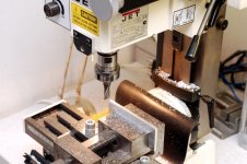
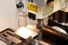
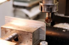
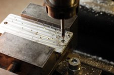
But I'm on the other side of the issue. Any device is better to start with a case, otherwise there is a risk that it will remain in the form of bare boards and wires. Found two old optical modems. Their enclosures are suitable for phonostage and headphone amplifier. Plastic panels, of course, are not suitable, according to the laws of the genre, the front panel should be thick aluminum and protrude beyond the body. But the rear panel is usually made thin and does not protrude beyond the edges. To round the corners, I bought a shaped cutter. This is still a panel blank, it is necessary to make the required holes in it, and at the end to grind the surface.
Attachments


The first suggestion has an advantage over the other two: it's a j-fet unity gain stage so you don't need to deal with additional phaseshift compensation while today's op amps don't really need any external help except impedance matching.Ad745 should be exceptionally good for your circuit and there should no need for external devices .The third stage is the genious one because it allows +3db SNR with jfet thermal matching properties.
Last edited:
Here's a case for spliting the topic...Theoretical talking was allowed by the OP, but this looks like hijacking a thread...Thank you! I also have a large collection of diagrams and articles on this topic. It takes some time to spend in the simulator.
But I'm on the other side of the issue. Any device is better to start with a case, otherwise there is a risk that it will remain in the form of bare boards and wires. Found two old optical modems. Their enclosures are suitable for phonostage and headphone amplifier. Plastic panels, of course, are not suitable, according to the laws of the genre, the front panel should be thick aluminum and protrude beyond the body. But the rear panel is usually made thin and does not protrude beyond the edges. To round the corners, I bought a shaped cutter. This is still a panel blank, it is necessary to make the required holes in it, and at the end to grind the surface.
I want to use a hybrid first stage for two reasons: 1) less noise, 2) more linearity due to high loop gain. The source follower on JFET will not provide additional gain, although the issue of the battle with correction will be removed.The first suggestion has an advantage over the other two: it's a j-fet unity gain stage so you don't need to deal with additional phaseshift compensation
That's right, op amps are capable of providing all the necessary parameters for the phono stage. This is confirmed by the video above - with an opamp you get a SNR of about 80 dB, which is quite enough. Therefore, I plan to make two versions of the amplifier - just an op-amp and with a hybrid input stage.while today's op amps don't really need any external help except impedance matching. Ad745 should be exceptionally good for your circuit and there should no need for external devices.
The use of a DC servo makes a second JFET unnecessary. And the input stage can be improved somewhat.The third stage is the genious one because it allows +3db SNR with jfet thermal matching properties.
I dont know. Design issues apply to any phono stage. Now I'm making a power supply, perhaps this will also be interesting.Here's a case for spliting the topic...Theoretical talking was allowed by the OP, but this looks like hijacking a thread...
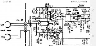
IF you are interested in low noise design, I recommend that you obtain "The Sound of Silence" by Burkhard Vogel and "Low Noise Electronic Design" by Motchenbacher. There is nothing new in low-noise design. By the way, you can do better than a TIA. With a little positive feedback you can design a negative input resistance amplifier. An inductive signal source, such as a phonograph cartridge, has a winding resistance which in combination with the inductance limits the low frequency response (puts a zero in the transfer function) even if the amplifier has zero input resistance. A negative input resistance amplifier can cancel some of the winding resistance and extend the low frequency response. You have to be careful with this method or you have an oscillator instead of an amplifier. You make an oscillator by placing a negative resistance across a resonant circuit. The method is shown in the attachment. The amplifier has combined negative and positive feedback to produce a negative input resistance.
Attachments
IF you are interested in low noise design, I recommend that you obtain "The Sound of Silence" by Burkhard Vogel and "Low Noise Electronic Design" by Motchenbacher.
Attachments
Yes, nothing new, but there may be small circuit design features that can be worked on.IF you are interested in low noise design, I recommend that you obtain "The Sound of Silence" by Burkhard Vogel and "Low Noise Electronic Design" by Motchenbacher. There is nothing new in low-noise design.
What is the advantage of negative input resistance compared to pole compensation with zero?By the way, you can do better than a TIA. With a little positive feedback you can design a negative input resistance amplifier. An inductive signal source, such as a phonograph cartridge, has a winding resistance which in combination with the inductance limits the low frequency response (puts a zero in the transfer function) even if the amplifier has zero input resistance. A negative input resistance amplifier can cancel some of the winding resistance and extend the low frequency response.
Both of these books widely use such a parameter as "noise figure", which for preamps with a predominantly inductive nature of the internal resistance of the signal source does not make sense.IF you are interested in low noise design, I recommend that you obtain "The Sound of Silence" by Burkhard Vogel and "Low Noise Electronic Design" by Motchenbacher.
Noise figure is very useful. Often the transistor or opamp manufacturer will have plots of noise figure vs frequency, or source resistance or collector current. These noise figure charts make it quite easy to select a suitable input transistor or FET for the preamp. The book by Vogel is all about preamp design.
Leoniv asked "What is the advantage of negative input resistance compared to pole compensation with zero?" The low frequency response is determined by the zero set by the resistance and inductance of the cartridge. The low frequency response is falling off, the SNR is decreasing and it cannot be improved by subsequent amplification. The negative input resistance amplifier extends the low frequency response and keeps the SNR high.
Leoniv asked "What is the advantage of negative input resistance compared to pole compensation with zero?" The low frequency response is determined by the zero set by the resistance and inductance of the cartridge. The low frequency response is falling off, the SNR is decreasing and it cannot be improved by subsequent amplification. The negative input resistance amplifier extends the low frequency response and keeps the SNR high.
No, there will be no improvement in SNR. If a negative input resistance compensates for the internal resistance of the source, this does not mean that the thermal noise of this resistance will be canceled out.The low frequency response is falling off, the SNR is decreasing and it cannot be improved by subsequent amplification. The negative input resistance amplifier extends the low frequency response and keeps the SNR high.
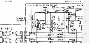
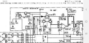
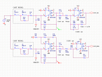
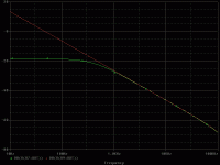
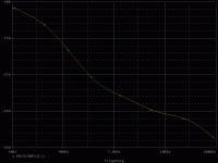
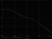
This is easy to check on the model. Above is a TIA circuit, below is a circuit with a negative input resistance. The frequency response curves at the output of the first stage show that the internal resistance of the cartridge is fully compensated - the curve has a constant slope of 6 dB / oct. The resulting frequency response is made the same. The noise spectral density curves for these two circuits are the same.
Attachments
The noise factor is defined as the ratio of the output noise power of a device to the portion thereof attributable to thermal noise in the input termination [ https://en.wikipedia.org/wiki/Noise_figure ]. The inductance of MM cartridge and PB head of taperecorder both have zero thermal noise, therefore noise figure is absolutely useless and its application leads to false results both in the calculation of the signal / noise, and in the noise optimization of phono or PB preamps.Noise figure is very useful.
Last edited:
No. I want to remind you that for two equal uncorrelated noise sources, their total sum RMS value is 1.41 each, and the most interesting thing is that their difference RMS value is also 1.41.The negative input resistance amplifier extends the low frequency response and keeps the SNR high.
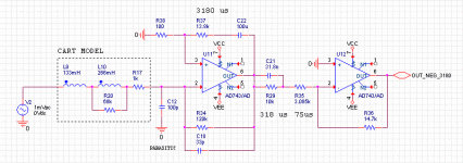
There is one more possibility - not to completely cancel the resistance of the cartridge winding, but to cancel it partially. In the AURAK amplifier, an additional resistor (positive resistance) was connected in series with the input in order to shift the pole for any cartridge to 500 μs (which is bad - noise increases). By adding negative resistance, you can shift the pole in the other direction to 3180 µs. To do this, the equality Lcart/(Rcart+Rin)=3180 μs (where Rin<0) must be observed. By adjusting the negative input resistance, this can be achieved for any cartridge. Not sure if this is a good idea - the noise stays the same.A negative input resistance amplifier can cancel some of the winding resistance and extend the low frequency response.
Attachments
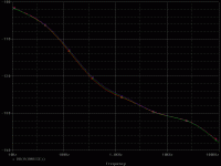
I think there is a misunderstanding. I said the negative input resistance amplifier could improve the low frequency response; I did not say it could improve the SNR. The negative input resistance does not cancel resistor noise. I am not sure what Mr. Sukhov is saying. Everybody knows that resistors generate noise and reactance's do not. You can use the noise figure plots to choose the bias current for the input device. I have attached some noise figure plots and it is obvious that the transistor should be biased at about 100 microamperes for a low noise preamp.
Attachments
The question was, how is negative input impedance better than conventional EQ to get the same response at low frequencies?I think there is a misunderstanding. I said the negative input resistance amplifier could improve the low frequency response; I did not say it could improve the SNR.
- Home
- Vendor's Bazaar
- Nick Sukhov SU-XXI MM Phono stage -85 dBA SN ratio...