I understand that, but this is a simple and elegant solution that won't take up much time or money!
Regards
Dave
Regards
Dave
Trials of other oscillators (phase shift types) are not giving results as good as the Wein Bridge; distortion is relatively high, unless gain is trimmed - which defeats the purpose of using this design.
Looks like the Wein Bridge is going to be the one used, as I originally fantasized..
Looks like the Wein Bridge is going to be the one used, as I originally fantasized..
New Technics
Hi Fellas
I've been following this fascinating thread as I'm totally new to DD technology. I have recently acquired my first dd turntable - a Micro MR-711 circa 1974. I have no speed or speed instability problems and would like to know (if you have the time), if there would be any major differences between the SP10 family of dd systems and that of my oldtimer Micro?
I got some translated blurb from Audio Database regarding the Micro's drive system"
"The direct-drive scheme using the DC servo motor by an electronic-circuitry control system is adopted as a drive system. The meter scheme of electronic circuitry adoption is adopted as 1/3 or 45rpm velocity checking. The zero point adjustment on this meter is proofread so that it may be in agreement with a constant-speed degree rotation of a motor using a frequency counter, and it is pursuing the accuracy more. Moreover, 33.3 speed control organisation in which 3 or 45rpm became independent, respectively is carried, and +-6% of fine tune is possible to a convention velocity".
What do you think of all this? Does the Technics system have any relevance here?
bulgin
Ah, Wein bridge... built one a long time ago. From what I recall, The Art of Electronics said that the GBW (gain-bandwidth product) of the op amp must be at least 20x the oscillator frequency. I also seem to remember that the signal gain within the oscillator had to be exactly x3. That particular application also required a constant amplitude, and I had to include a FET-based constant voltage amplifier... memories...
Re: New Technics
Ja, but "wine" sounds better... 😀
bulgin said:Isn't it Wien bridge?
Ja, but "wine" sounds better... 😀
Hi Bulgin
Could you prease transrate that into Engrish.
I'll take a look for technical information on that motor & post soon.
Shaun:
Yes, the WIEN bridge osc needs a gain of precisely 3x, no more no less. Which in real life is impossible to achieve. Hence the need for some sort of automatic gain compensation system - Ge diodes, thermistor, or a filament lamp.
In theory, the phase shift osc shouldn't make more demands on the GBP, because it uses two amplifiers, not one. And a gain of just over 4 is the theoretical minimum. Still, it tends to clip much more severely than the Wien. And the quadrature osc, with gain compensation added, becomes unreliable and reluctant to always start.
I used to call it a 'Vine' bridge, but a friend at university always referred to it as 'Ween' - somehow it unfortunately rubbed off on me, and with it a tendency to spell it wrong; that and the fact that the Austrian version of Vienna is Wein. Internet references seem to use both, interchangeably - more proof not to cite the www as a reliable source!
The meter scheme of electronic-circuitry adoption is adopted as 33 1/3 or 45rpm velocity checking. The zero point adjustment on this meter is proofread so that it may be in agreement with a constant-speed degree rotation of a motor using a frequency counter, and it is pursuing the accuracy more.
Photo of the motor here:
http://audio-database.com/MICRO/player/mr-711-e.html
2.0kg plater
From
http://de.geocities.com/bc1a69/micro_eng.html
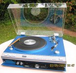
"Micro MR-711: This is the Micro that started it all back in 1972. The 10" tonearm is the MA-202. This is a very heavy deck made out of solid metal, platter weighing around 4pds the whole deck around 40pds. Speed control was achieved by using a moving coil that was induced by the platter. You can vary the speed by +-6% by opening a little box under the deck which houses the control knobs.
Micro DD-100: Introduced in 1976 the DD-100 was the first quartz-controlled Micro Seiki. Build quality of these decks is simply exceptional as with most top-of-the-line Micros. These decks are rarely seen in Europe or the USA but are quite often seen in Asia.
Here you see the control-unit of a DD-100. The quartz-lock can be switched off like with the later DQX-1000."
I think what they might be saying in the Japanese-English is that the speed setpoint is calibrated at manufacture with a frequency counter.
It seems the MR-711 has a drive system very like the SL1200 MARK 1, (not Mark2).
It uses velocity feedback, but no phase detection (no quartz reference) This is not always a bad thing - good wow & flutter figures can be maintained, BUT the absolute speed may drift with time & temperature.
The Technics SP10 system is similar, but for the crystal frequency reference. The Technics has a bigger motor and more heavy-duty electronics - that would be due to its aspirations for broadcast use where it has to be able to start & be up to speed within a fraction of a second.
That die cast chassis is certainly something to admire, and I love the door in the front that opens to store the extra pickup and tools!
Since it is old, it may be interesting to check the speed setpoints - there are two trimpots at the bottom of the motor, my guess is they are the 33 & 45 rpm setpoints. But unless you can hear a speed problem, that might be all for nought. Without an accurate reference (frequency counter) it will be impossible to get it aligned to the original spec.
If you were really keen on it, you could add a quartz lock to the Micro. A complete circuit diagram (schematic) would be a prerequite.
I'm poking the last few components onto the 'main' PCB layout, and have now started to think that MAYBE I should re-do it with a separate PSU PCB.
This will give tweakers a much easier method of changing & using different power supplies - if they want. (At this point I sing: "These foolish things remind me of you")
My initial choice of one pcb was that the power output stages should be electrically close to the PSU for good current delivery and grounding, but if I do the layouts dilligently, they can behave as a single PCB (almost).
Plus point 2: Two small pcbs are easier to make than one large one.
I'm poking the last few components onto the 'main' PCB layout, and have now started to think that MAYBE I should re-do it with a separate PSU PCB.
This will give tweakers a much easier method of changing & using different power supplies - if they want. (At this point I sing: "These foolish things remind me of you")
My initial choice of one pcb was that the power output stages should be electrically close to the PSU for good current delivery and grounding, but if I do the layouts dilligently, they can behave as a single PCB (almost).
Plus point 2: Two small pcbs are easier to make than one large one.
Agree fully with TWO boards!! IF you go for one perhaps it could have a clear line for physical division so that we can convert to two boards?
Many thanks for all your work!!
1 or two PCB's
I like the idea of having the power supply on seperate boards for ease of maintenance and the possibility of upgrading the power supply alone. I'm new to this thread, but as a SP10 owner am very interested.
Has anybody tried converting the neon strobe to high intensity LED's.
Please don't believe the web based theory that changing the capacitors in the 140V supply with cure strobe failures it doesn't.
Regards to all
Has anybody tried converting the neon strobe to high intensity LED's.
Please don't believe the web based theory that changing the capacitors in the 140V supply with cure strobe failures it doesn't.l
I think I have seen mention of it somewhere, but I didn't pay much attention to it. In principle, not difficult since the strobe signal is generated at TTL logic level anyway.
Neon gas discharge tubes age - replacing the lamp might be indicated after so many years. Last time I bought neon lamps (about 5 years ago, I bough a bag of 100) they were 7 US cents each.
PLL INFO UPDATE:
If anyone was freaked out by the logic diagram of the CD4035 as used in a PLL, I have redrawn the diagram, leaving out all the unimportant bits - bottom of
http://web.eject.co.za/s8nspawn/sp10web/sp10page3.htm
A state diagram comming soon!
Last edited:
New Technics
Hi Steerpike
Thanks for the comprehensive explanation😀 Since re-commissioning the Micro, I have kept careful watch for speed issues and there's nothing serious except for the meter which shows no deviation from centre if the speed adjustment knobs are used. These, you have to push in and turn to increase or decrease by the stated 6%. I'm not sure if the meter should show a deviation to + or - from centre, if the speed is deliberately adjusted too fast or too slow.
Regards
bulgin
Attachments
nothing serious except for the meter which shows no deviation from centre if the speed adjustment knobs are used. These, you have to push in and turn to increase or decrease by the stated 6%. I'm not sure if the meter should show a deviation to + or - from centre, if the speed is deliberately adjusted too fast or too slow.
It makes sense that the meter is wired to monitor the error signal in the feedback path. The error signal is mathematically given by:
Error(t) = Setpoint(t) - TachoMeasured(t)
If you change the pitch control knob, you are changing the setpoint. Once the feedback system has stabilized, the error should again be driven to zero.
Since this turntable has no quartz crystal, it wouldn't really be useful to have a meter that reads deviation from '33.333333...', since it doesn't really have an *absolute* reference. But reading the error signal is useful, in that it shows that the servo system is operating correctly, regardless of how accurate its reference setpoint is.
In non-quartz servos, the setpoint is in reality a voltage reference, so it's not that the control system is in any way inferior to a quartz system its just that the reference is less stable in regard to temperature fluctuations or power supply variation.
(An example of this is the ReVox B790. When you switch it to 'varispeed', all it does is switch the timing reference from the quartz crystal to a 555 timer oscillator. The PLL servo system is not modified or reconfigured at all.)
*****
Re: the SP10.
I haven't updated here in a while ; I have made a few additions to my own page on that topic.
Currently, the 'new dual board' PCB layouts under construction.
& my software model of the state-machine-PLL just didn't want to co-operate, so I'm leaning more towards building it and measuring actual performance, rather than trying to make the PC predict it theoretically.
New Technics
Hi Shaun
Like in hand braking the spinning platter? No deflection at all. The meter remains rock steady centred on zero.
@ Steerpike
Thanks for your kind explanations again. One day I hope to aspire to an SP10🙂 and hear what all the fuss is about.
bulgin
Does it deflect when you deliberately slow it down manually?
Hi Shaun
Like in hand braking the spinning platter? No deflection at all. The meter remains rock steady centred on zero.
@ Steerpike
Thanks for your kind explanations again. One day I hope to aspire to an SP10🙂 and hear what all the fuss is about.
bulgin
- Home
- Source & Line
- Analogue Source
- New Technics SP10 motor controller specification