count me in ....
Steerpike
as a new owner of the 10 Mk2 I am doing the 35 yr maintenance thing
so that it is kind of in the range it should be ..which will have to do me for now ;
however I agree w/ Rich , Lew and the others that the successful completion of your endeavours would really breath new life into this wonderful 'antique' piece !
good luck & BIG thanks for your efforts
Bernard
re off the TT
I had been planning to move the electronics after changing out the caps and it seemed that many voiced support for this idea .I don't have a proven technical reason for this but it seemed like a reasonable move given the freedom we DIYers have to get the electronics 'hash' from the motor away from the / MC cartridge /music into a separate enclosure.
however I received an interesting email from a member of a different forum who has lots of technical experience & worked on the SP10M2 he asked me 'why' I wanted to move to outboard ...??
he comments below and some of the points he brings up seem valid
"Are you concerned about "digital hash" intruding into the low-level signals from the cartridge? Did you read about this "mod" somewhere?
The reason I ask is that moving the circuitry off the frame will require a LOT of "re-engineering" in order for it to succeed. Not only that, it is VERY possible that the extended "umbilical cord" will introduce MUCH more opportunity to pick up external noise - even with a shielded cord.
It will also increase the likelihood that signals traveling down those LONG wire lengths may interfere with each other. The framework of the turntable, along with the bottom cover, form a nearly total shield over ALL of the digital circuitry. This is a Faraday Shield and it is VERY effective at keeping noise and RF completely contained.
Quite frankly, I can't see any real advantage to moving the circuitry "outboard" from the turntable, but I would LOVE to hear better advice on the subject. I simply don't know the "definitive" answer on this. I tend to operate along the philosophy of "If it ain't broke, don't FIX it!" Unless there is a real REASON to move this stuff, I don't see a need to "
personally I understand that a new PS & controller would make sense to have in a separate enclosure ( its all new form factor)
but as far as the existing electronics I am not sure ... from your post Brian it suggests that you noticed none of these negatives ?
what was the umbilical ? new cable & shielded ? length 3' ?
comments appreciated
brianco said:For my part I would be perfectly happy if a simple 33rpm function - with no frills other than say an on-board =/- 5% speed adjuster, were to be the outcome of this project. I also would require that the PS+Controller were capable of being cabinet mounted at say 3' distance from the turntable itself. My present TT is a SP10Mk11P (ex.BBC) and all on board electronics were successfully mounted as an out-board unit connected by an umbilical. (It worked for five years this way but now has a 'dead' problem which I am not qualified to diagnose. A new, simpler, DIY unit would be the more economic option to rebuilding the existing boards.)
The difference between on and off TT electronics is very big indeed and the extra trouble is far outweighed by the improvement in all aspects of the resultant sound quality.
I had been planning to move the electronics after changing out the caps and it seemed that many voiced support for this idea .I don't have a proven technical reason for this but it seemed like a reasonable move given the freedom we DIYers have to get the electronics 'hash' from the motor away from the / MC cartridge /music into a separate enclosure.
however I received an interesting email from a member of a different forum who has lots of technical experience & worked on the SP10M2 he asked me 'why' I wanted to move to outboard ...??
he comments below and some of the points he brings up seem valid
"Are you concerned about "digital hash" intruding into the low-level signals from the cartridge? Did you read about this "mod" somewhere?
The reason I ask is that moving the circuitry off the frame will require a LOT of "re-engineering" in order for it to succeed. Not only that, it is VERY possible that the extended "umbilical cord" will introduce MUCH more opportunity to pick up external noise - even with a shielded cord.
It will also increase the likelihood that signals traveling down those LONG wire lengths may interfere with each other. The framework of the turntable, along with the bottom cover, form a nearly total shield over ALL of the digital circuitry. This is a Faraday Shield and it is VERY effective at keeping noise and RF completely contained.
Quite frankly, I can't see any real advantage to moving the circuitry "outboard" from the turntable, but I would LOVE to hear better advice on the subject. I simply don't know the "definitive" answer on this. I tend to operate along the philosophy of "If it ain't broke, don't FIX it!" Unless there is a real REASON to move this stuff, I don't see a need to "
personally I understand that a new PS & controller would make sense to have in a separate enclosure ( its all new form factor)
but as far as the existing electronics I am not sure ... from your post Brian it suggests that you noticed none of these negatives ?
what was the umbilical ? new cable & shielded ? length 3' ?
comments appreciated
The analogue frequencies involved are LOW - AC currents are below 20Hz in frequency, so the possibility of them causing audible interference is minimal. These currents have to exist in the motor itself - no way of moving that away - unless you use a 3-inch thick platter.
The tacho signal is of higher frequency, but it is in the millivolt range - no interference caused by that! BUT it is susceptible to external noise pickup, as is an audio cable. Noise on the tacho signal is just about the worst possible place to have it, in a feedback control system. (Here might be a good place for a true balanced input to the controller!)
The only 'noisy' cable is the excitation voltage for the variable reluctance phase detector coils. That's at 50khz. A screened cable there is a good idea. It exists in the motor too, and is shielded by the rotor and the plater.
Long (thin) cables to the motor have exactly the same negative effect as long loudspeaker cables: added resistance which reduces the damping factor of the drive amplifier. But the normal operating currents are not high - tens of milliamps, nothing requiring fat exitic cabling.
Yet I suspect these effects are minimal: Can you hear the difference between 1m and 3m of speaker cable? Can you hear the difference between 50cm and 1m of phono cable? And these are cables where the actual audio is being conducted!
The connetion to the motor is by 12 conductors. You could make these as long or a short as you like, it doesn't involve any changes to the design.
The digital electronics is likely the most objectionable - theoretically anyway.
My design is two boards - the analogue power supply / driver stage, and the digital control section. The analogue power section could be kept close to the motor (for all the above reasons), and the digital board put a short distance away, which I think is a good compromise. The two boards are connected by a flat ribbon cable.
My design is two boards - the analogue power supply / driver stage, and the digital control section. The analogue power section could be kept close to the motor (for all the above reasons), and the digital board put a short distance away, which I think is a good compromise. The two boards are connected by a flat ribbon cable. [/B][/QUOTE]
Steerpike
thanks for the good info
just wondering though if keeping the analogue /PS close to the motor
do you mean under it as is the case now w/ the controller ..OR more likely beside it w/ the digital section farther away ?
I was leaning towards moving the old stuff as I alluded to but instead I will just update caps etc and wait for the new design
did you see the Japanese translation where the designer put it all in one box ?
best Bernard
Attachments
My own personal plan is to put it all in one box, under the platter.
The digital section probably inside its own sheet steel box - like the cans they put the RF section of TV tuners inside.
The digital section probably inside its own sheet steel box - like the cans they put the RF section of TV tuners inside.
sorry ...do you mean another 'new' box under the plinth or ...under the platter where it is now ?
I have no plinth. The motor will go into a wood plinth, i.e., the top of a cabinet with wood sides and base - basically a six-sided box. Electronics in the bottom of that box.
Well that was my plan.
MAYBE I'll want to experiment!
Well that was my plan.
MAYBE I'll want to experiment!
My system has a 2 feet umbilical so that the PS can be on a seperate shelf to the motor unit in its plinth.
The idea of having the PS/controller unit in a box within the plinth does not mean that it must be connected to the plinth. A recess in the plinth can allow for the box to be on the same support shelf with no contact with the plinth. The resultant shorter cable requirement may well overcome other issues.
However it would be difficult adopt this system with a maker's obsidian plinth. My aim is to build a plinth for the motor alone and to ditch the original top plate unit - I long ago stripped out the mechanical brake.
 BUT first i need the new PS/Controller!!
The idea of having the PS/controller unit in a box within the plinth does not mean that it must be connected to the plinth. A recess in the plinth can allow for the box to be on the same support shelf with no contact with the plinth. The resultant shorter cable requirement may well overcome other issues.
However it would be difficult adopt this system with a maker's obsidian plinth. My aim is to build a plinth for the motor alone and to ditch the original top plate unit - I long ago stripped out the mechanical brake.
BUT first i need the new PS/Controller!!Steerpike said:I have no plinth. The motor will go into a wood plinth, i.e., the top of a cabinet with wood sides and base - basically a six-sided box.
brianco said:My aim is to build a plinth for the motor alone and to ditch the original top plate unit - I long ago stripped out the mechanical brake.
Here's my design for one such plinth (see bottom of page).
Shaun,
Thank you....I have a similar plinth concept, only somewhat larger....that way it can be reduced, but if it is to hide the electronics it may well remain large!
Has anyone got a good power supply schematic designed to produce the raw voltages needed to supply the control and drive sections? Such a design, using today's components should be more stable than the original and easy to build.
Many thanks
brianco said:Has anyone got a good power supply schematic designed to produce the raw voltages needed to supply the control and drive sections? Such a design, using today's components should be more stable than the original and easy to build.
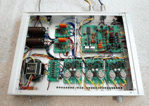
Hi, Brian.
I'm new to this thread, but I thought it was time to jump in. I recently procured an SP-10MkII without the power supply. I designed a new supply that seems to make the platter spin properly (!) and the lights light. I won't have a plinth constructed for another week or 2, so I can't say how it sounds on an absolute basis. However, I will be able to compare it to my Teac TN-400 "MagneFloat" TT on a similar plinth, which I like better than my HW-19MkIV+.
Anyway, the supply is pretty straight-forward. The current demands aren't all that great (+32.5V @ 220ma, +5V @ 280ma, and +140V @ 5ma). However, I did observe that the motor current spikes up to around 1A for about a second at startup and for about 1/2 second at turnoff, so be advised.
The supply uses transformers I had on hand. The 30VAC transformer is probably a bit of overkill, but this is audio, right? The +140V supply is very sleazy. I've done this "reverse connection" thing for bias supplies in a tube amp and low current tube guitar preamps, which is what gave me the idea. There aren't a lot of 100-120V low current transformers around. I get about 85VAC out of the reverse-connected transformer, which I feed into a voltage doubler. Crude but effective. At some point, I'd like to remove the neon lamp in the strobe and replace it with an LED so I can run it off a low voltage.
Those are Fairchild "Stealth" diodes for rectifiers. I also use Panasonic FC's for the low voltage filtering and ED's for the HV. Can't wait to hear it.
JL
Attachments
JL, many thanks....
....for taking the trouble. I'll let you know how it goes!
Any comments from anyone on JL's schematic?
....for taking the trouble. I'll let you know how it goes!
Any comments from anyone on JL's schematic?
Steerpike said:
For the moment, it's just a figure that appears in an equation to determine the value of certain capacitors and resistors. What I want to do eventually is have the microprocessor automatically take measurements of the motor mechanics all by itself, and then compute its own feedback parameters accordingly. So after changing mats, or platters etc. you'd just push the 'align' button, and it would do its thing - much like tape decks that do automatic bias alignment.
And 16-2/3 RPM is a requirement for me, so it will be a 4 speed.
I think the software should have a 'feature' that if anyone tries to 'scratch' with the turntable, it shuts off and won't re-start for 24 hours!
I read your post and to me you come off as if you do not know what scratching really is.
It can be done and has been done to death on less capable decks than the SP-10MkII, the SL12x0 for instance.
"Scratching" is a lousy term for the activity itself.
Scratching means to momentarily halt or manually turn the vinyl opposite the playing direction for artistic reasons.
The way this is accomplish probably defers a LOT from your perception:
A special thin mat is used called a slip mat. This mat has a very slippery surface facing down on the turntable platter and a grippy surface facing up against the vinyl record.
Thus stopping the vinyls movement requires a lot of less effort than I think you give this principle credit for.
And moving the vinyl in the direction opposite playing does not require a whole lot of power either. This is done routinely by DJs using the soft part the their fingers, just under the nail.
The SP-10 family gives the principle of letting the vinyl go and quickly letting it pick up speed to play a section very good properties to work with. it is the analog way to sample and repeat in the old days.
Look around I am confident that several videos on the internet show this principle.
Technics manufactures slipmats for professionals, and decks that can stand up to this. Technics is also one the main sponsors of the annual International DJ Championship competition.
I really do not see this as something bad, ill or not to do.
There are countelss reason why you do not want to do this. ranging from, the cost of the stylus/cart or record all the way up to you're not good enough at it to warrant keeping up doing it.
I have seen and heard some truly amazing stuff done using turntables and a mixer.
This is USUALLY not the type of use you employ using your fathers Koetsu MC cartridge and his rare collection of 1st issue half-speed mastered classical music. But a DJ will have another take on it and use any snippet for effect.
I never DJs myself and never tried my hand at mixing. With arthritis in family gene pool this would probably not be a long career anyway. And I should have started when I was a kid in the 80s.
For now I will hope this thread ends up in more pictures of working stuff and resort to fixing my gear up as best as I can.
Vinyl would not be this popular today without DJs. So go and hug your local DJ. Keep saving old decks from waste deposits, neglect and people who do not know what they are doing.
-Mikkel
There is a seller on eBay who is selling new after market Power Supplies for the SP-10 Mk II. I forget which seller ID he has but it looks small and can probably be built into at least just as many plinths as the factory one.
I have recently read an article about the Rubato turntable mat, from England. It is in the current issue of High Fidelity in Denmark (4-2009). it is a 1.7 Kilos copper plate which look good and is reported to improve the sound. I might go for one on next month budget.
No words anywhere about the added mass of the platter and any start up difficulties. But then you're talking about using the 10Kilo MkIII platter with the electronics designed to pull a 2,9 stock Mk II platter so 1.7 Kilo really isn't much I guess.
I have two SP-10MkII in my Technics collection and I am in the process of getting the SH-10B3 plinths completed for them. I am afraid I am not hard core enough to tell the tiny differences of playing a record with a blue label or an orange label like I suspect some people claim to can. But the engineer spirit of this thread is a good factor that kept me reading all the pages of the thread.
Btw the same Highi Fidelity mag 4-2009 also has an article about a swedish guy who secured himself a pair of Technics AFS-100 speakers. 175 kilo each. They'd be scraping the ceiling in my apartment and I am struggling to have enough room for my current collection as it is not everything can be set up up for use at the same time. 🙁 🙁
-Mikkel
I've started a web write-up of the project developments. So far, not much that hasn't been posted in this forum already.
(I will mention updates to my web page here in this forum, so no need to go check my page every day to see if its changed, you can rely on the email notifications from DIYAUDIO.COM)
http://web.eject.co.za/s8nspawn/sp10web/sp10.htm (a few internal cross-reference bugs still, and somehow my editor decided to eliminate every occurrence of the word 'the' - I may not have spotted all when I put them back! )
great idea
Steerpike
for a dedicated page to the project , which hopefully will move forward
also an impressive array of projects on your toys page as well ...
pretty good credentials ..!
Steerpike
for a dedicated page to the project , which hopefully will move forward
also an impressive array of projects on your toys page as well ...
pretty good credentials ..!
- Home
- Source & Line
- Analogue Source
- New Technics SP10 motor controller specification