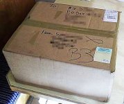
A great big thank you to Shaun O. for the SP10 platter & chassis which arrived today!
Apart from being wonderful for me, it's also going to make things much better for other DIYers, since now I can make PC boards that physically fit the SP10 chassis and its 'bathtub'.
That means the current PCB layout must be modified to fit the 'new' physical dimensions.
Now it is imperative that the PSU be a separate board & box, since it will not fit comfortably into the bathtub.
----
I'm curious to know Shaun, how did you come by this chassis without motor? Or did you take the motor & PCBs out for another SP10?
Attachments
Last edited:
You guessed right; it was a donor turntable. Sadly its motor has play in the bearing. Unheard of apart from this example.
Great!
However, although I have the factory full obsidian plinth I have a gut feeling that others are better. The Kaneta plinth, but in natural slate coupled with Albert Porter's vibration damper (see here:
<http://forum.audiogon.com/cgi-bin/fr.pl?vaslt&1227334719&read&keyw&zzsp10>
makes a LOT of gut felt sense. My electronics are already off-board - and still non-functioning !!😡). I should be able to sell the original plinth to pay for proper machining of a slate plinth. (see here:
<http://db.audioasylum.com/cgi/m.mpl?forum=vinyl&n=832368&highlight=mikel>
It is well worth a search of both sites above for sp10....LOTS of v./ good stuff! (Someone sold the basic deck and PS for around US$7,500 recently!!!!!)
However if you can design the boards to fit within the tin-can/motor unit it will help many. But it seems that most who are rebuilding/optimising their SP10 are going off-board. Many are ex BBC units and come with a 19" rack mount like mine. I can post the dimensions if useful).
Last edited:
Just checked the links in my post above: you will have to paste them to your browser! How do you enable HTML for links?
It is well worth a search of both sites above for sp10
A lot of pretty pictures! Things to lust after for sure!
However if you can design the boards to fit within the tin-can/motor unit it will help many. But it seems that most who are rebuilding/optimising their SP10 are going off-board.
I think I'll make the boards so that they CAN fit in the bathtub; but then people can put them outside in an independant housing if they want that too.
I do think that the power output stage should be physically close to the motor - I think i wrote about that further back.
My key-pad and display will have to be outboard anyway - no way of physically fitting that into the existing chassis - unless the keypad is in the form of an IR remote control.
A basic drawing of the 19-inch rack layout would be interesting to see all the same, how they chose to lay everything out.
Great - again!
That option is a clear winner.... everyone can use it . I agree that the OB - if the main boards are ob - should be as close as reasonable. My umbilical is about 0.5 meters. I had the TT on a wall mount rack with the PS suspended on strings below. It worked for a very long time until it just died on the job! The rack PS is in a (internal) 37cmx32cmx10cm case. The mains Tx and Ps use only 10/11cm on the LH side! The rest I believe was for eq units and for MC stages etc. It is reasonably easy to get the original boards in there.
I'll take a couple of pics tomorrow....its Midnight here just now...and post them.
That option is a clear winner.... everyone can use it
. I agree that the OB - if the main boards are ob - should be as close as reasonable. My umbilical is about 0.5 meters. I had the TT on a wall mount rack with the PS suspended on strings below. It worked for a very long time until it just died on the job! The rack PS is in a (internal) 37cmx32cmx10cm case. The mains Tx and Ps use only 10/11cm on the LH side! The rest I believe was for eq units and for MC stages etc. It is reasonably easy to get the original boards in there.I'll take a couple of pics tomorrow....its Midnight here just now...and post them.
Last edited:
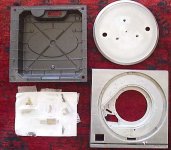
I've been mapping out all the threaded holes in the SP10 die-casting, so I can make the p.c. boards mounting holes match up. Its quite a tricky process, since they are at several different heights. Mostly done now though.
The SP10 mk-1 looks different, but mk-2 and mk-2a look as if they have the same casting (from the mediocre servive manual scans I have).
The SP10 mk-1 looks different, but mk-2 and mk-2a look as if they have the same casting (from the mediocre servive manual scans I have).
Attachments

Hi Steerpike
Dunno if you noticed that the holes are marked with the lengths of the respective standoffs...? Could perhaps be of some significance.
Dunno if you noticed that the holes are marked with the lengths of the respective standoffs...? Could perhaps be of some significance.
Dunno if you noticed that the holes are marked with the lengths of the respective standoffs...? Could perhaps be of some significance.
I did see that. Measuring between the stand-offs is easy enough: the mildly tricky part is getting the relative distances between the stand-offs and the 'other' holes, and the boundaries of the 'bathtub', since the whole thing is quite 'lumpy'! Oh, an figuring out how much clearance I'll have for heatsinks!
Now a query on operation: from what I can make out, the brake solenoid energises for braking, and is not-energised during play, and when the AC power is off, there is no platter brake engaged. This seems an odd way round to do it.
Many people seem to remove the brake band altogether.
Now a query on operation: from what I can make out, the brake solenoid energises for braking, and is not-energised during play, and when the AC power is off, there is no platter brake engaged. This seems an odd way round to do it.
Yep, that's how it functions.
Many people seem to remove the brake band altogether.
I think this is an intuitive "upgrade". The brake (often?) drags, making a hissing sound. I don't know how much this actually contributes to mechanical noise. The SL-1200 uses reverse mode to apply brakes (I suspect that the SP10 uses electronics and mechanical brake). The mechanical brake is only really useful for studio use, IMO.
I would love it if the electronic brake in the new controller could have speed/rotation sensor to control its effectiveness: my project is a Kaneta-style plinth, so it uses just the motor.
Last edited:
I would love it if the electronic brake in the new controller could have speed/rotation sensor to control its effectiveness: my project is a Kaneta-style plinth, so it uses just the motor.
I'm planning on an electronic brake that measures speed to apply braking force. It's almost a necessity, since if the turntable can be programmed to play at almost any speed between say 15 and 80rpm, the brake force would be different in every case. It gets a little complicated - needing to sense direction too, since we don't want the braking force turning into runaway reverse drive!
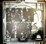
Meantime, here's a pic of some 'mock' boards, just cut to verify size/clearance and whether I mapped the mounting stand-offs in the right places.
I decided now the power supply should go completely 'outside' the turntable - a change from my original plan. Since there is physically no way to get the transformer into the SP10 'bathtub' chassis, the trafo HAS to be in its own box, so the regulators etc. may as well go there too.
Attachments
Reference Clock?
Steerpike,
Have you decided what your reference clock source is going to be?
Chris
Steerpike,
Have you decided what your reference clock source is going to be?
Chris
Have you decided what your reference clock source is going to be?
An ordinary quartz crystal as the master oscillator of a microcontroller. Probably something cheap and easy to source - one of the 'standard' frequencies - 4MHz, 6MHz,10MHz (or 4.43MHz - of which I have A LOT! it's the PAL colour carrier frequ.)
A few questions...
Steerpike,
After reading (most) of the documentation on your website that describes your design intentions, I have a few questions:
1) In the PLL State Diagram, State1 has no transition path in the event of a Phase Lag, i.e. P/S (7) = 1. Following your circuit, it looks to me like a Phase Lag while in State1 will then transition to State3.
Similarly the MSB (Q1) has nothing that is dependent upon it (no external logic uses its output) and can possibly be removed. If you have a Phase Lead while in State1, you should be able to stay in Stage1, therefore shrinking the State Machine to 4 states.
Please correct me if I'm wrong as I'm probably missing something.
2) Your Tacho amplifier doesn't show the generation of the tacho signal (the frequency -> Voltage converted signal). IS this an omission or something that is already done by the circuitry (i.e. something you won't have to re-invent the wheel on).
Chris
1) In the PLL State Diagram, State1 has no transition path in the event of a Phase Lag, i.e. P/S (7) = 1. Following your circuit, it looks to me like a Phase Lag while in State1 will then transition to State3.
Yes, correct. State 1 is a logically unnecessary state, but the hardware (using a CD4035) is simplified by allowing this particular redundant transition sequence.
Similarly the MSB (Q1) has nothing that is dependent upon it (no external logic uses its output) and can possibly be removed.
Yes , right again. Q1 (pin 13) is connected to nothing. The chip just happens to be a four-bit shift register, and only 3 flip-flops are required.
Ad you point out, strictly, only 4 states are required, so it would be possible to cut the logic down to 2 flip-flops.
This isn't a design of my own, it's an analysis of an existing circuit used by Studer, that I was thinking of using. I have not tried to improve it. Yet.
2) Your Tacho amplifier doesn't show the generation of the tacho signal (the frequency -> Voltage converted signal).
It is JUST an amplifier. My tests showed the tacho signal is rather 'difficult': small and highly variable amplitude. So the first task was to get a reliable square-wave signal, dependant ONLY on frequency. From that will come the F/V conversion (still comming).
Other questions to get me up to speed....
Sorry if these have been answered before (or that I'm not phrasing the questions correctly)....
When the Phase Detect circuitry detects that a speed-up is necessary, how much is the expected tach signal expected to increase by in the next cycle?
Or, in other words, 1) is the amount of speed boost expected to creep up slowly until the final speed is reached or 2) is the speed boost expected to overshoot the final speed (and then settle down due to the design of the PLL)?
I'm writing a simulation model (in Verilog) to help me understand how fast the State machine can 1) catch up from static start 2) respond to subtle changes (like speed, err vinyl, modulations) and the like. I'd like to add some real world approximations to the amount the tachometer increases to expect.
p.s. As an aside: My own SP-10 arrived yesterday (sans-motor). Where is the best site to go to for details on how to disassemble it, add the proper amount of bearing oil, etc.
Last edited:
When the Phase Detect circuitry detects that a speed-up is necessary, how much is the expected tach signal expected to increase by in the next cycle?
The tacho signal will vary almost infinitessimally - really tiny amounts. The PLL has a range of 1/190 of a revolution, and phase changes can occur with no average speed error at all.
The PLL and velocity tacho work almost independantly of each other. The tacho brings the speed into the approximate range, after which phase control is taken over by the PLL subsystem.
The ratios of their respective effectiveness are still to be determined though.
Or, in other words, 1) is the amount of speed boost expected to creep up slowly until the final speed is reached or 2) is the speed boost expected to overshoot the final speed (and then settle down due to the design of the PLL)?
It should creep up fast. with minimal or zero overshoot. There is always a trade-off between accuracy and speed of response. It all comes down to whether you choose to underdamp, critially damp, or overdamp the control system. Usually fractionally underdamped is the best compromise, which give a little overshoot, but faster dynamics than critically damped.
I'm writing a simulation model (in Verilog) to help me understand how fast the State machine can 1) catch up from static start 2) respond to subtle changes (like speed, err vinyl, modulations) and the like. I'd like to add some real world approximations to the amount the tachometer increases to expect.
Generally, low gain in the tacho is better, and large gain in the compensator.
I can't give exact numbers yet - I haven't got enough practical measurements done. But as far as the ASM tacho/PLL goes, the output voltage goes almost instantaneously to max until correct speed is reached. This is usually overkill, and a low-pass filter is placed after the PLL output to temper its response.
p.s. As an aside: My own SP-10 arrived yesterday (sans-motor). Where is the best site to go to for details on how to disassemble it, add the proper amount of bearing oil, etc.
I think the vinyl engine has service manuals for download.
I'm hoping you mean "sans PSU", not without a motor?
Have you got the Mk2 or the Mk2A ?
Yep, that's how it functions.
I think this is an intuitive "upgrade". The brake (often?) drags, making a hissing sound. I don't know how much this actually contributes to mechanical noise. The SL-1200 uses reverse mode to apply brakes (I suspect that the SP10 uses electronics and mechanical brake). The mechanical brake is only really useful for studio use, IMO.
I would love it if the electronic brake in the new controller could have speed/rotation sensor to control its effectiveness: my project is a Kaneta-style plinth, so it uses just the motor.
My mech. brake was removed as part of a big tweeking-out. How much that contributes to the much lower than BBC guise noise floor I simply don't know. But we could see no use for it in normal usage.
- Home
- Source & Line
- Analogue Source
- New Technics SP10 motor controller specification