So I see there’s multiple takeout spots for Speaker + along w the +/- charge for the output stage. Should all be combined or is just one takeout point cool? I figure combining all points could be slightly beneficial but not sure
You should be fine either way but if you had them printed in 1oz and plan on driving the bias fairly high, you can jump them between the heatsink and PCB board if you like with insulated wire. The traces are pretty large on these and I believe they are doubled front and back.
speaker wires - just wire them all (2 for 6deep, 3 for 8deep), and solder together at speaker terminal
that's clever arranging
learned that from Pa
that's clever arranging
learned that from Pa

speaker wires - just wire them all (2 for 6deep, 3 for 8deep), and solder together at speaker terminal
Oh!!! I thought you were supposed to use just one… this is much cooler.
😎
Last edited:

So I am thinking of putting one of these together for someone. They want 100w in class A which means monoblocks. I have enjoyed my stasis so much that I recommended it to them for driving a difficult load with bass. I would like to keep the rail voltage low'ish and bias them hard. I used 28vac transformer with 39v rails in mine and have tested it up to 83 watts. Do you think 45 rails would get me to 100w?
5U deluxe case from the store
Antek 100va 35v transformer
DIYaudio standard CRC boards
22000 63v caps
Zen's 8 pair board + aux going to 7 pairs on the 2nd board.
These would be the speakers:
Analysis Omega
Not the most difficult load but not easy. Let me know your thoughts and any special considerations that I should make.
What’s the math say?
45V rails is a max of 90V pk-pk.
The emitter resistors are going to steal a couple of volts at full swing, so let’s say 2.5v in each direction, so total swing will be around 85V.
85V pk-pk * .3535 = 30Vrms
Power output is Vrms^2/load
30^2=900
900/8ohm=112W
900/4ohm=225W
Assuming the amp can swing 85V, yes, you’ll make 100W
Alright. Looks like 45v rails are perfect. A little more or less wattage will likely not be noticeable. Thank you 6L6!
What is the .3535 figure stand for?
What is the .3535 figure stand for?
Last edited:
1/(2 * sqrt(2) ) ~ 0.3535. Factor to convert peak to peak voltage (assuming we have sine wave) into RMS voltage.
Dennis/6L6,
Is the loss of 5V with BJT's pretty standard (2.5V for positive and 2.5V for negative half the sinewave) ? For MOSFETS I recall it's more like a loss of 6-7 volts total yes? Just curious, since this is all theory and we won't know until we bench test the amp.
Mike,
1000VA is a good size though (your link is labelled as 100VA😛 but it links to a 1000VA Antek toroid).
Good luck with the build Mike!
Best,
Anand.
D. Self offers the rule-of-thumb that BJT follower output stages -- including their emitter resistors -- can only pull the amplifier output within ~ 6 volts of each rail. This figure includes all of: the output transistors, their emitter resistors, the driver transistors, and the non-rail-to-rail swing out of the VAS stage.
It would be even greater than 6V for MOSFET follower output stages, which is why Nelson Pass often includes bootstrap circuits to drive the gates of MOSFET followers beyond the rails
It would be even greater than 6V for MOSFET follower output stages, which is why Nelson Pass often includes bootstrap circuits to drive the gates of MOSFET followers beyond the rails
The original SA/1 amp came with 1000VA toroid transformer, and two 60k mfd caps. When I copied my originals I used a 2.4kVA transformer and eight 78k mfd caps. Made a noticeable improvement in the sound, mostly by being able to push the bias up considerable.
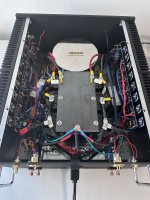
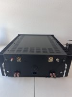
Finally got this thing up and running. Used Pico’s chassis, 8 deep boards. Started off at 44.5 unloaded volts and after biasing, came out to 41 volts so guessing im getting a little over 100 watts if my math is right. It’s biased to 150ma which is getting me a little over 50c
Attachments

- Home
- Amplifiers
- Pass Labs
- New Stasis front end