It’s a good gig if you can get it. 😂😂😂😂😂what to do with those - flying to work, to build amps?

Of all 3 frequent flyers I know of here, only one is frequently flying to build amps
rest, 2 of them, are "just" flying
ZM is not even flying
rest, 2 of them, are "just" flying
ZM is not even flying

anyway, why bother
build it, listen and then take all the time for simulations
build it, listen and then take all the time for simulations
Hi everyone,
I have been reading this thread with great interest !
My purpose is to mod some of my lateral mosfet amps with a real good frontend . Most are equipped with lateral Hitachi mosfets .
I have contacted Z.M. yesterday and he's planning the same ..
Question :
Does any of you guys here have some FE boards available to sell to me ? Perhaps including the jfets and other bjt?
Sincerely,
Paul
Hello
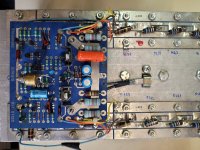
My Stasis 3 amp has been repaired, and the circuit boards are in very poor condition.
I would like to salvage most of the original components and reassemble them on new PCBs.
I'm going to order PCBs, but I don't know which ones to choose. I'm thinking of getting the larger ones, those made by Mr. Pass.
Can you tell me the dimensions of this PCB?
On one channel, four TO3s were replaced, and only one on the other channel.All the other TO3s are original.
I'll have to redo some of the wiring, because the repairer also burned the wires in addition to damaging the PCBs.
Here are some photos to illustrate.
Attachments
I would like to salvage most of the original components and reassemble them on new PCBs.
if speaking about FE pcbs, do not
use all new parts, cost is trivial
Thank you, yes, I'm talking about the FE PCB.
I would like to use the NP FE PCB.
Is it possible to have the complete part list for this PCB ?
I would like to use the NP FE PCB.
Is it possible to have the complete part list for this PCB ?
I'm one of the few that built one of these. I didn't use Papa's OG FE board but ZM FE boards with 8 deep output boards. I also created my own parts list which i did not save. I didn't skimp on parts since this build was for my father so i never thought of saving my list. Looking back, i probably should have.
I cant fully recall but there was one builder that used the OG FE boards to bring his dying stasis back to life. It may be in this thread or in a separate thread. I'll see if i can find it
I cant fully recall but there was one builder that used the OG FE boards to bring his dying stasis back to life. It may be in this thread or in a separate thread. I'll see if i can find it
Heres the thread
Hi Gents.
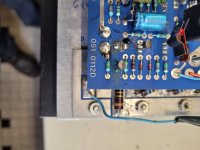
Recently bought this Stasis 2 as faulty ( the only way I could ever afford one )
Symptoms were : slowly over time was brought up to 240v using a variac , then used for a week until smoke was seen and then the left channel went down.
I’m no engineer but I can replace parts so I’m hoping someone can steer me in the right direction.
Any idea which component(s) have failed and caused the burn ? ( see photo also )
Any assistance would be greatly appreciated.
- TheFinisher
- Replies: 514
- Forum: Pass Labs
Okay, I'll make a list of what I need.By the time I receive the boards, I'll have time to look.few Boyz made it, maybe they can help
though, best to make your own list from schmtc
if in doubt about any of parts, just ask
there are Gerbers for all pcbs, and maybe someone is having few surplus ones
For the board dimensions, should I request 140 mm (4.5") x 104 mm (4.2")?
I made a shopping cart for 5 boards on this site: https://www.smart-prototyping.com/PCB-Prototyping.html
I don't know which is best, this will be my first time ordering blank PCBs.
I helped The Finisher with his Stasis 2 rebuild in the thread referenced at post #1514, we used the NP FE board and it worked fine and fitted in well. As part of that rebuild, we installed all new TO3 outputs, new emitter 3watt resistors, new PSU caps and new PSU diode bridge at the same time. Any questions just ask here.
I built an entirely new Stasis with Zen Mods FE and 8 way OS and it works perfectly - and sounds great.
I built an entirely new Stasis with Zen Mods FE and 8 way OS and it works perfectly - and sounds great.
By rereading the topic from the beginning, I found the answer to my question, it was in the first post:
"Attached are various schematics and graphics and also the gerber files
for the circuit board, which was made my pcbway.com, who will ask
what dimensions are, which is 5.5" x 3.5" "
"Attached are various schematics and graphics and also the gerber files
for the circuit board, which was made my pcbway.com, who will ask
what dimensions are, which is 5.5" x 3.5" "
That is NP's layout. Zen Mod also has a layout further into the thread that is more compact and the pcb is a lot smaller.
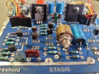
Just some comments from my build.
I changed the value of the pot P1 to 1K, so that I could adjust the DC offset more easily around 0V. Mine runs at around 1-2mVDC offset.
I changed the resistor R19 in the bias circuit to 510R so that the bias pot when set to max resistance for start up gave 0mA Iq, With the resistor at 221R I could not get the the Iq min to get down to zero with the bias pot P2 at max resistance.
Thermostat T shown as a normally open type is actually a normally closed type that opens when the heatsink temp gets to above 65 deg C or so, your existing thermostats should be OK for each channel.
Thermistor TH1 in the bias circuit must be in contact with the heatsink and is a 2K NTC type. The bias is adjusted finally with the chassis all bolted up and the lid sitting on top. It will take a couple of hours to reach thermal equilibrium.
- Home
- Amplifiers
- Pass Labs
- New Stasis front end