Sure, if you work closely with your PCB layout artist to avoid design deficiencies / weaknesses (crosstalk, mutual coupling, ground contamination, etc) then yes, it certainly would be possible.
@Mark Johnson: Thank you Mark. I have full confidence in my layout team. They did an exellent job with my ACA.
With regards to the schematic, where would you put it, and what values would you use?
With regards to the schematic, where would you put it, and what values would you use?
I'm not especially interested in, or enthusiastic about, "adding some local R/C filtering to the new Stasis Front End" . Sure, it's possible; nope, I'm not going to participate. Thanks but I decline your offer.
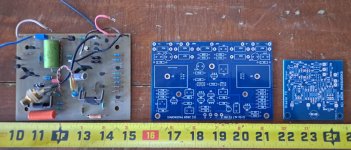
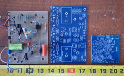
I would look into using Mr Pass's gerber as a starting point. Zemod's boards are pretty small for the mounting locations on the threshold amps. Although, he did add a couple of alterations that you could implement into yours if you like. To make the board look more stock'ish, I would remove the cascode section. stretch the board out on the input side to give yourself a location to add holes. However, it is hard to even see the boards when they are in place. Especially with the cover on...
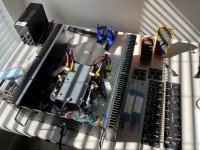
I didn't alter the gerber. I just made a metal bracket to use with the boards and moved the mounting stud over one interval (to the next transistor I believe.
You can look at the amp that I implemented the boards onto. I didn't use the stock wires as that arrangement doesn't line up with the new boards.
I have all three boards, the original, Zen's and Mr Pass's. I will try to pull them out later so you can get an idea.
Regarding the noise, I tested this front end through a pair of LaScalas that I have in my garage. There was no real discernable noise. You had to put your ear right up to the tweeter to hear the noise. Now I have a CRC power supply in that amp so even less noise.
Make sure that the power supply voltage will cooperate with the front end. I had trouble trying to use it at 80v. At 39v, it behaves quite nicely.
My last suggestion would be to relocate the bias and offset pot either towards the back of the board facing towards the back of the amplifier, or maybe to the side and mirror image the boards. One board would be for right channel one would be for left to be able to access them with the top cover off.
With the stock power supply caps, the bias pots are real close and hard to get to.
With the stock power supply caps, the bias pots are real close and hard to get to.
@Mikerodrig27: My plan exactly. Stay as close to Papa's layout as possible, resize boards, move holes, connections to fit stock wiring, components facing heat-sink, easy to reach pots.
I only need to find out if it makes sense to add some local RC-filtering, to maybe reduce the noise from the power-supply.
The only reason this has become a 'problem' to me, after living happily with my S/150 for many years, is that I have recently built other Papa-amps, and I have learned that a power-amp can be absolutely dead-silent. My Thresholds are not.
By RC filtering, you are wanting to have a resistor and then a Capacitor on the supply per rail on the front end? I would try without the RC filtering. If you add RC filtering to the front end, the voltage will be lower than on the output board. I don't think that is a big deal but I don't know for sure.
On my amp, the chassis ground and the power supply ground were one. I separated them with a CL60 thermister per channel which was the main reason for reducing the noise. I never tried this with the old setup but doing it with the new front end worked very well. Also, there is a ground connection to each heatsink that you will need to remove if you separate the grounds.
Measure your DC offset and see what they are. It should be below 50mv. If it is higher, it could be something like the an issue with the differential Jfet on the input board, or a bad transistor on the output.
Last edited:
Awwww phooey... I should have asked. Boards already ordered.
Good to know there's boards already made, I'm sure people will want to build this.
Good to know there's boards already made, I'm sure people will want to build this.
Okay no problem. Yes, it is a nice amp. I would assume it is a bit better with the new ouput stage and the more modern transistors.
Keep us up to date! It will be cool to see how things work out. 🙂
Keep us up to date! It will be cool to see how things work out. 🙂
Got a couple questions on zen mod’s FE
1) are the Jfets the only piece that need to be matched?
2) the SMD on the back are optional?
1) are the Jfets the only piece that need to be matched?
2) the SMD on the back are optional?

- Home
- Amplifiers
- Pass Labs
- New Stasis front end