(I was speaking generically....)
Yes, this is a good looking DC SOA. Also, the temperature coefficient
at the currents we are thinking about don't look very problematic.
Yes, this is a good looking DC SOA. Also, the temperature coefficient
at the currents we are thinking about don't look very problematic.
Its nice of you to drop in, especially for a n00b who just want to learn and earn and golden star 😀(I was speaking generically....)
Yes, this is a good looking DC SOA. Also, the temperature coefficient
at the currents we are thinking about don't look very problematic.
Do you consider the UJ3N065025K3S plausible for the F5-F6 series, optimization and biasing aside, or perhaps a completely different architecture to start with ?
- EDIT -
Almost forgot about the SIT range...
Last edited:
F5 requires complementary P and N parts, so it's out. F6 would be a candidate,
as would the SE amplifiers.
Plausible? Yes, but I haven't tried it that I recall.
as would the SE amplifiers.
Plausible? Yes, but I haven't tried it that I recall.
JFETs conduct in both directions, so drain and source can be "inverted", unless there is a special case. "same sex" as Zen Mod call it. Backed up by Erno Borbely. Ofc I can't speak for all architectures. Just looked at the F5 - Enhancement mode MOSFET .. so that would certainly need to have the voltage polarity inverted (Q3/Q4).F5 requires complementary P and N parts, so it's out. F6 would be a candidate,
as would the SE amplifiers.
Plausible? Yes, but I haven't tried it that I recall.
If I'm way off... just correct me.
Its should more or less just be flipping the V polarity since the UnitedSiC is N-chn deplition, so the P-chn Enhanced in the Q4 position is the only one who need a polarity flip so that both Q3 and Q4 is -V
🙂
🙂
You would want to examine this issue on a case by case basis.
Some Jfets are truly symmetrical. Many, not so much.
Some Jfets are truly symmetrical. Many, not so much.
Oh absolutely. Testing the UnitedSiC JFET would first need to happen on the test bench so one can check as many things as possible, perform endurance test and so forth. Something I might do eventually unless someone gets it done before me.You would want to examine this issue on a case by case basis.
Some Jfets are truly symmetrical. Many, not so much.
Oneminde
This thread has been quiet for a while, so lets look at some news. Read article and comment what you think.
UF3SC065007K4S - data sheet is attached.
This SiC FET device is based on a unique ‘cascode’ circuit configuration, in which a normally-on SiC JFET is co-packaged with a Si MOSFET to produce a normally-off SiC FET device.
UnitedSiC Titles New SiC FETs as the “Lowest RDS(on) SiC Power Devices on the Planet” - News
Attachments
I would just use the SiC jfet as is, in a design similar to a classic 2-stage SE partial feedback tube amp with output transformer. Here's an example -
"SiC Puppy SE Amp Using Semisouth 085 JFET
It's time I revisited this design with some improvements, most notably a follower stage to get around the nasty gate leakage of the SiC jfet.
"SiC Puppy SE Amp Using Semisouth 085 JFET
It's time I revisited this design with some improvements, most notably a follower stage to get around the nasty gate leakage of the SiC jfet.
Last edited:
if you count on Ugs range of 6V or so and that doesn't give you troubles, why not
UJC being enhancement, UJN being depletion mode
UJC being enhancement, UJN being depletion mode
Hi.I have found some Sic mosfets UJ3C120040K3S from local distributor.Can they be used for audio? J2 amp maybe? Any advantages over IRFP240? Maybe i can use a pair of them instead of 2 pairs of IRFP240?
This SiC FET device is based on a unique ‘cascode’ circuit
configuration, in which a normally-on SiC JFET is co-packaged with a Si
MOSFET to produce a normally-off SiC FET device. The device’s
standard gate-drive characteristics allows for a true “drop-in
replacement” to Si IGBTs, Si FETs, SiC MOSFETs or Si superjunction
devices. Available in the TO-247-3L package, this device exhibits ultralow gate charge and exceptional reverse recovery characteristics,
making it ideal for switching inductive loads, and any application
requiring standard gate drive.
Attachments
it seems as Treshold Ugs (p.5) is in range of 5V, so smidfe higher than usual mosfets
also SOA graph (Fig. 17) is showing that part is good for DC, our normal range of currents and voltages
https://unitedsic.com/datasheets/DS_UJ3C120040K3S.pdf
also SOA graph (Fig. 17) is showing that part is good for DC, our normal range of currents and voltages
https://unitedsic.com/datasheets/DS_UJ3C120040K3S.pdf
They have a high price in Mouser/Digikey.I have already bought them in a good price.Is it worth to build amp with them,any advantages? Or should i sell them?Regards
The SOA looks good but there is no transconductance information. How good is your price? 🙂
Look at it this way - if you figure out they can be used to build amps with AND they sound good and measure well, you can get better $ perhaps.
Look at it this way - if you figure out they can be used to build amps with AND they sound good and measure well, you can get better $ perhaps.
They have a high price in Mouser/Digikey.I have already bought them in a good price.Is it worth to build amp with them,any advantages? Or should i sell them?Regards
no other way of finding that, than testing in potential circuit

Hi.Mark on ACA forum wrote:
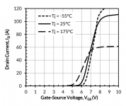
""Because their transconductance dIout/dVin is not constant unless Iout > 10 amperes, which is well outside the range of standard bias currents in audio gear, and well outside the range of standard heat dissipation capability of audio enclosures. It's laughably beyond the max possible current of the ACA power supply and howlingly beyond the max possible dissipation of the ACA heatsinks and chassis.
Here's the transconductance plot from the manufacturer's datasheet ""
Attachments
that's academic until real test
send me 4 and I'll try them in few circs
don't expect them back
or, simply, try them by yourself
send me 4 and I'll try them in few circs
don't expect them back
or, simply, try them by yourself
- Home
- Amplifiers
- Pass Labs
- new SiC JFETs?