OK Ladies and gentlemen the results are in for the Cree C2M0160120D versus the IRFP240 used in a partly built F6.
I'm using an HA5002 high speed buffer chip as the front end instead of the matched JFET's driving the Jensen transformer and slightly higher supply voltages +-29VDC as I had access to a large dual secondary 24VAC 1500
va transformer. I have been using this power supply and heatsink with the IRFP240's for a couple of months now and it has been rock solid Bias and zero offset and it sounds fantastic.
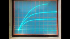
I have been running about 1.1 to 1.2 AMP bias and as you can see in the picture the same for the Cree's.

The next is the IRFP240 with a square wave at approx 5KHz as Nelson had shown in the F6 article.

The next is the same but with the Cree.

Unfortunately there is not much difference very slight less rounding on the leading edge but I can only put this down to the Jensen and the associated circuitry as the spec's for the Cree are at least a 1/3rd input capacitance. I think that other amplifier topologies might be better suited for this device. One thing of interest to the tube crowd looking at the curve traces on the previous posts and when the triangle wave was driven into hard clipping it formed a beautiful sine wave much more so than the IRFP240 it just flat topped.
How does it sound? Well I ran out of time last night but will build both to compare with the same conditions and report back.
One good thing about the Cree it was a simple drop in to the F6 and it biased nicely. (I'm using the 9.1volt zener to achieve a wider spread if needed) The Vgs appears to be similar to the IRFP240 around 4.5 Vdc.
Cannot wait to see what people are going to do with these in other amps. 🙂
I'm using an HA5002 high speed buffer chip as the front end instead of the matched JFET's driving the Jensen transformer and slightly higher supply voltages +-29VDC as I had access to a large dual secondary 24VAC 1500
va transformer. I have been using this power supply and heatsink with the IRFP240's for a couple of months now and it has been rock solid Bias and zero offset and it sounds fantastic.
I have been running about 1.1 to 1.2 AMP bias and as you can see in the picture the same for the Cree's.
The next is the IRFP240 with a square wave at approx 5KHz as Nelson had shown in the F6 article.
The next is the same but with the Cree.
Unfortunately there is not much difference very slight less rounding on the leading edge but I can only put this down to the Jensen and the associated circuitry as the spec's for the Cree are at least a 1/3rd input capacitance. I think that other amplifier topologies might be better suited for this device. One thing of interest to the tube crowd looking at the curve traces on the previous posts and when the triangle wave was driven into hard clipping it formed a beautiful sine wave much more so than the IRFP240 it just flat topped.
How does it sound? Well I ran out of time last night but will build both to compare with the same conditions and report back.
One good thing about the Cree it was a simple drop in to the F6 and it biased nicely. (I'm using the 9.1volt zener to achieve a wider spread if needed) The Vgs appears to be similar to the IRFP240 around 4.5 Vdc.
Cannot wait to see what people are going to do with these in other amps. 🙂
Attachments

You'd have to cascode to make use of that region I suppose
Join Date: Jun 2010
Location: Southeast
Yes I suppose you would. It seems a bit strange to operate a 1700 volt component at such low voltage. But it might sound interesting....
Last edited:
That's why I think once the tube builders get to use these as replacements they will be using higher voltages. But Nelson had discovered that these switching transistors made excellent amplifier components and used them to great success which is why thinking outside the box benefits us all.
One more comparison.....
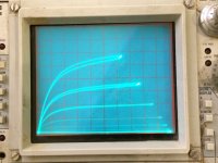
The SiC curve looked really familiar. Here are the curves for
a 2SK170 compared to the Cree 1700 volt part. Many similarities in shape and distribution (at least to my eyes). By the way I forgot to mention that I used the 10 ohm drain resistor load to make the Cree curve set. So as I understand it the end points of the curves describe a 10 ohm load line.
Attachments
Last edited:
One more comparison.....
The SiC curve looked really familiar. Here are the curves for
a 2SK170 compared to the Cree 1700 volt part. Many similarities in shape and distribution (at least to my eyes). By the way I forgot to mention that I used the 10 ohm drain resistor load to make the Cree curve set. So as I understand it the end points of the curves describe a 10 ohm load line.
This one is for the Cree
Attachments
OK Ladies and gentlemen the results are in for the Cree C2M0160120D versus the IRFP240 used in a partly built F6.
EDIT
Unfortunately there is not much difference very slight less rounding on the leading edge but I can only put this down to the Jensen and the associated circuitry as the spec's for the Cree are at least a 1/3rd input capacitance. I think that other amplifier topologies might be better suited for this device. One thing of interest to the tube crowd looking at the curve traces on the previous posts and when the triangle wave was driven into hard clipping it formed a beautiful sine wave much more so than the IRFP240 it just flat topped.
🙂
formantjim,
Very interesting and well written account of your use of the Cree SiC mosfet. Thank you for sharing that, and to all who are following this thread.
I think there is a significant difference in the square wave comparison. To me it looks like your bandwidth has increased. Can your audio generator be swept higher? If you could increase it to the point where the square wave becomes a sine wave, that would give you an idea of the bandwidth.
Also very interesting that the overload characteristics are graceful rather than abrupt. I bet that it sounds much less bad when overdriven than the IRFP240 version.
This one is for the Cree
Does this mean the CREE part may be a good substitute for the K170?
Thanks mikegranger. I'm going to try to get better readings but my first test this evening will be listening to it. I have never tried or tested the K170 so I cannot comment.
No, I didn't mean to imply that at all. Sorry if it seemed that way. They are very different animals. The K170 is a small signal, low voltage, low power, depletion mode low noise Jfet. The Crees are very high voltage, high current, high power, enhancement Mosfets. I just thought it interesting that the curves, when adjusted so that they fit on the same oscilloscope screen, look to me very similar in shape. I am just hoping the Crees will sound good in the right circuits like the K170's do.Does this mean the CREE part may be a good substitute for the K170?
@formantjim Nice one! Your commentary on the clipping behavior is interesting as well. Any idea on the gain of the F6 circuit now with the cree parts in place?
I have just spent the last couple of hours listening to the F6 with the Cree and the gain is about the same as far as I can tell. The sound is very subtle in its projection I feel the bass is a little tighter and highs a little clearer but I think a little more burn in is required.
I don't think the Crees handle the bias as well as the IRFP as I'm running the same bias about 1.2A due to the slightly higher supply voltage and the temporary heatsink is really toasty. So much so I turned the bias down to about 900mA I think once installed in the 5U monster case each Cree with it's own heatsink larger than the shared one currently being used for testing we take the bias even higher to say 1.5A.
My conclusion is that the F6 is not the best Amp for the Crees and more suited to the F5 and such without the transformer limiting the bandwidth. But since I have got these devices they will be going in the completed F6 as the F6 is a fantastic sounding amp so stable and easy to setup.
Excellent - I'm glad to hear it sounds good to your ears as I have for the most part finished off my F6 build with the cree parts. I'm particularly pleased to hear you say the bias is stable as I built mine with single turn trimmers for the bias(out of impatience!), which is making adjusting challenging, and may require a partial rebuild.
With regards other builds, I'm considering having a play with a Mini Aleph build utilising the Cree parts. The challenge will be the 8V or so bias to drive the part!
With regards other builds, I'm considering having a play with a Mini Aleph build utilising the Cree parts. The challenge will be the 8V or so bias to drive the part!
A bit of random googling revealed this SICJfet does anyone know anything about it?
I tried to google the manufacturer SiCED and came up a blank. Who is SiCED?
Hi,
Siced is a daughter of Siemens(Infineon).
A couple of years ago, they developed the 1200V SIC-JFET and SIC-Diodes.
They behaved like JFETs, i.e depletion mode.
After Siemens presented the Transistors and Diodes on their website Siced somehow returned into the dark depths of internet again.
jauu
Calvin
Hi asbrinv I would love to hear about you experience with the biasing maybe I got lucky or it is just a very clever simple design. Wait a minute it is a clever simple design!🙂🙂
No major issues - I was just impatient when I built it originally. I used a single turn trimmer for the bias and offset and given the zener i used was 10V the range of adjustment on the trimmer was tiny/touchy. I stripped the whole build back yesterday and changed the trimmers to multi turn parts so I should be all good now.
Burn Burn Burn
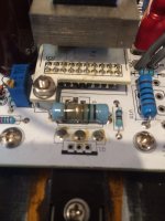
...or not, perhaps. I used a value of 0R68 for R1 (instead of the listed 0R56) mainly because thats what I had on hand at the time.
Unfortunately, after biasing up to about 1.7A it now looks like the below.
Guess I'll need to replace that wee guy as well 😱
...or not, perhaps. I used a value of 0R68 for R1 (instead of the listed 0R56) mainly because thats what I had on hand at the time.
Unfortunately, after biasing up to about 1.7A it now looks like the below.
Guess I'll need to replace that wee guy as well 😱
Attachments
Last edited:
Here is my current test bed F6 with the HA5002 front end driving the Jensen with a 47ohm in series to limit the current. This is using the Cree SiC FET's bias 1.2Amps.

Formantjim,Here is my current test bed F6 with the HA5002 front end driving the Jensen with a 47ohm in series to limit the current. This is using the Cree SiC FET's bias 1.2Amps.
View attachment 501668
Very nice testbed! Are you still liking the Cree sound??
Thanks for the picture, and for keeping us in the loop.
- Home
- Amplifiers
- Pass Labs
- new SiC JFETs?