My post was a joke to Jim, based on his comment in another thread 🙂
https://www.diyaudio.com/community/...ations-with-ideal-drivers.380658/post-6977833I have grudgingly accepted that this is true.


I got the joke, Fluid... and it is even funnier than you think. In my first conversations with Headshake back in mid 2020, he asked me if I was using VituixCad to simulate the whole "all-axis" response of my speakers, and I told him that learning VituixCad seemed like a lot of work for little value. Ha Ha I am laughing so hard I can still feel the shoe in my stomach...
This project is based on your early guidance to minimize the baffle gain on the tweeter by making the baffle as small as possible around the tweeter.
This project is based on your early guidance to minimize the baffle gain on the tweeter by making the baffle as small as possible around the tweeter.
Nht was great products.
I can't say about hifi, but in pro their A20 monitors have been quite well accepted in my country. They had some very small mini monitors which was great too.
I don't know why they didn't get more successful? Too much concurence?
I can't say about hifi, but in pro their A20 monitors have been quite well accepted in my country. They had some very small mini monitors which was great too.
I don't know why they didn't get more successful? Too much concurence?
Last edited:
I got the joke, Fluid... and it is even funnier than you think. In my first conversations with Headshake back in mid 2020, he asked me if I was using VituixCad to simulate the whole "all-axis" response of my speakers, and I told him that learning VituixCad seemed like a lot of work for little value. Ha Ha I am laughing so hard I can still feel the shoe in my stomach...
This project is based on your early guidance to minimize the baffle gain on the tweeter by making the baffle as small as possible around the tweeter.
Cognitive dissonance. We all face it.
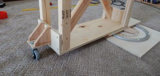
My new roller table for vertical polar measurements. If I have time tomorrow, I will collect the polar measurements, and we shall see how it compares to the predicted.
Nice design! Were you a mechanical or civil engineer (structural) in a past life? 😉
Looks like it could with-stand at least 300lbs of downforce.
Btw, what turntable product did you use? The metallic bit in the picture with the ball bearings.
I used this https://www.rockler.com/lazy-susan-heavy-duty-swivel
I was an aerospace structures engineer. My field was metal fatigue, loads monitoring, and structural integrity. The people on my team had a diverse engineering educational background. Some where civil, some mechanical (like me), some were aeronautical, some were TAM (theoretical applied mechanics). A mix of BS, MS, and PhD. Lots of statistics, lots of big huge numeric analysis codes which took hours to run. Speaker stuff is WAAAYYY more fun.
I was an aerospace structures engineer. My field was metal fatigue, loads monitoring, and structural integrity. The people on my team had a diverse engineering educational background. Some where civil, some mechanical (like me), some were aeronautical, some were TAM (theoretical applied mechanics). A mix of BS, MS, and PhD. Lots of statistics, lots of big huge numeric analysis codes which took hours to run. Speaker stuff is WAAAYYY more fun.
Oh tell me about it!. The trick these days is to find something whose shipping cost doesn't cost more than the product. Ah the curses of living in remote land down under... that "$49" lazy susan now costs $180 all up when shipped to Australia...
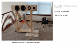
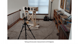
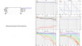
I completed the vertical polar measurements, and I re-measured the horizontal polar measurements so that I could maximize the consistency between the horizontal and polar. I measured from 0 to 180, and 0 to -180 for both horizontal and vertical.
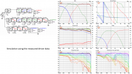
I really like the feature in VituixCad which converts impulse response (*.pir) to frequency response. It can quickly translate the whole polar set.
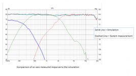
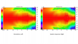
Comparing the system level measurements to the VCad simulation, the results look good. The on-axis response is within +/- 0.5 dB from 100 Hz to 20 kHz compared to simulation. The Horizontal polar responses are very consistent with simulation. The DI and ERDI are within 1 dB of simulation, and at most frequencies they are within 0.5 dB.
So I am satisfied that the simulation accurately reflects measured reality. This gives me the confidence that I can make changes and adjustments on the basis of simulation without needing to do a full system measurement again.
Now my next decision is whether to assemble the second speaker now, and listen to them for a while, or move forward with sanding, veneering, and applying finish.
I really like the feature in VituixCad which converts impulse response (*.pir) to frequency response. It can quickly translate the whole polar set.
Comparing the system level measurements to the VCad simulation, the results look good. The on-axis response is within +/- 0.5 dB from 100 Hz to 20 kHz compared to simulation. The Horizontal polar responses are very consistent with simulation. The DI and ERDI are within 1 dB of simulation, and at most frequencies they are within 0.5 dB.
So I am satisfied that the simulation accurately reflects measured reality. This gives me the confidence that I can make changes and adjustments on the basis of simulation without needing to do a full system measurement again.
Now my next decision is whether to assemble the second speaker now, and listen to them for a while, or move forward with sanding, veneering, and applying finish.
Attachments

Here’s my 2 cents. Actually worth probably closer to two Australian micropesos due to inflation.
once you build a pair of speakers you will end up listening and listening and listening and less motivated to fine tune your crossover. And as you know the crossover can make or break your speaker.
I can still see a large phase mismatch between your mid and tweeter. This has a major effect in audio images and should be corrected.
does the Hypex FA series have the ability to store a few crossovers?
I would at least have three or four on hand that you can switch and compare instantly and in short-medium term, and see which sounds more lifelike or natural to you.
after a few days weeks or months once you’re in bliss; then build your second speaker for stereo. Listening is in mono is more discriminating and less likely be stunned by the special effects of stereo.
the delayed gratification will be worth it.
The phase mismatch is an intentional feature of the 3rd order crossover at 2k. The quasi-LR3 crossover should have a 90 degree phase shift between mid and tweeter, and both should be -6 dB down at the crossover frequency. What makes the quasi-LR3 so special? When combined with the right CTC driver spacing (1.2x crossover wavelength), it can produce a very smooth directivity index.
My earlier projects used an LR4 crossover between the mid and tweeter, so of course they were in phase with each other. However, it is very difficult to get an LR4 to have a smooth DI unless the CTC spacing is 1/3 wavelength or less, and 1/4 wavelength is better. This is just not possible with most mids and tweeters.
Both Kimmo and Fluid have written about this (I take no credit, I just followed their magic formula).
The main motivation for this project is that I am curious if I will like the sound.
Jim are you measuring each driver on it's own axis or measuring all drivers from a fixed position?
When I measured the drivers individually, each driver was on its own axis. Horizontal polar data only. This data was used in the simulation.
For system level testing, I am using a fixed position, and doing both horizontal and vertical polar responses.
For system level testing, I am using a fixed position, and doing both horizontal and vertical polar responses.
Last edited:
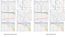
I thought I would expand a bit on post # 213, and what is going on with the quasi-LR3 filter.
I made a new simulation using LR4 at the crossover from mid to tweeter... staying with a nominal 2 kHz. There were some minor changes in the EQ and delays that were required to get a good flat response.
In the results you can see that, on-axis, there is very little difference... actually the LR4 is slightly smoother on axis... but the off axis responses show some differences. The DI curve for the LR4 is more lumpy, and it shows a gradual decrease of about 1.7 dB from 1200 Hz to 4000 Hz. Since the goal for this project is to optimize the DI performance, the quasi-LR3 is technically superior. Amir over at ASR would probably say the LR4 version has a "directivity error". In truth, I don't know how audible a 1.7 dB variation in DI might be.
I intend to listen carefully to both these options, as well as others. I am really curious as to what I will prefer, in my room.
Attachments


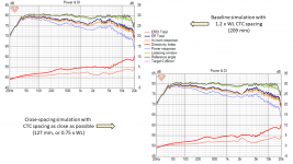
Regarding Center-To-Center spacing of the mid and tweeter.
This simulation shows the difference between my baseline with 1.2 x wavelength spacing (209 mm) and an alternate simulation with 127 mm spacing. 127 mm is the tightest possible spacing of an SB15 and SB26 (touching), and it is equivalent to 0.75 x WL at 2000 Hz.
The tight spacing introduces some lumpiness to the DI and ERDI curves. As expected, the on-axis curve does not change. Once again, we are faced with trying to judge how much DI lumpiness is too much... ? Only listening can answer that question.
Attachments
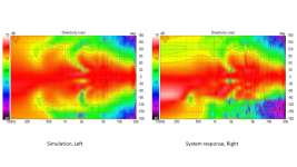
Jim, the more I kook at it, the peaking in the off axis responses between 2 and 5K seems like it will cause trouble if it is real and not partly a measurement artefact. I wonder if this is some mid range baffle diffraction as the tapers don't do anything for the mid due to the angle and the higher CTC spacing. The fact that the on axis between simulated and measured is close but not the off axis responses would give me some pause.
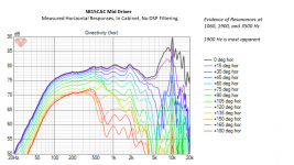
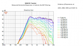
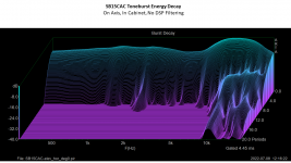
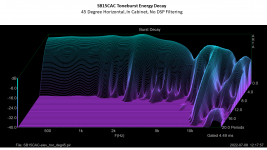
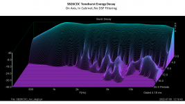
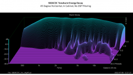
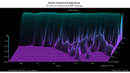
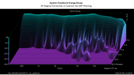
Well I definitely have some resonances, particularly in the 2k area of the midrange driver. It could be resonances in the drivers, but Hificompass did not measure a 2k resonance on the SB15NBAC which is nearly identical to this SB15CAC. In theory it could be a cabinet resonance, but the conventional wisdom is that cabinet resonances are miniscule above 1k.
I currently use no driver isolation on the mid and woofers, they are simply screwed down hard to the cabinet. I want to review Augerpro's work to see what he recommended for driver isolation. Perhaps this will reduce the impact.
The resonances I am seeing at 2k are in the 2 dB range, which is probably audible, but only just barely audible. The other resonances are closer to 1 dB and I am not too concerned about those. I am open to any theories as to the source of the resonance. I am open to ideas on how to mitigate...
j.
Attachments
The 2kHz hump and also around 1k look uniform across most angles, you could just EQ them out. Power response in post #183 follows nicely listening window and on axis response, just EQ them nice.
You could do impedance sweep and free air measurements to see if its from the construct or inherent with the driver. Could be mode in the box coming through the cone or something. Or just use the EQ where its good at 🙂
You could do impedance sweep and free air measurements to see if its from the construct or inherent with the driver. Could be mode in the box coming through the cone or something. Or just use the EQ where its good at 🙂
Last edited:
- Home
- Loudspeakers
- Multi-Way
- New Project - tower 3-way with twin 8s