This looks vaguely familiar. You out did me with the bevels on the top, I gave up after the cuts on the sides, I was a afraid of destroying the cabinets by making the top cut.Measurements start tomorrow... Impedance and near field to start with.
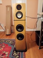
It is very satisfying to have reached this point.
j.
Attachments

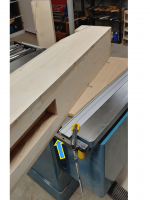
The bevels were the most challenging part. My table saw was almost too small for the job. In the attached photo you can see that I could not use my rip fence. I needed more space on the left side of the blade, so I had to clamp a straight edge to the table. Even then, I had just an inch of clearance. This difficulty is due to the height of the cabinet. If it were only 20 inches high, there would be no problem.
I am reluctant to build such a large cabinet with deep beveled facets in the future. I would be more inclined to make the cabinet in two parts and stack them. It looks like you made yours in two parts Mtidge, yes? Very nice looking work.
j.
I am reluctant to build such a large cabinet with deep beveled facets in the future. I would be more inclined to make the cabinet in two parts and stack them. It looks like you made yours in two parts Mtidge, yes? Very nice looking work.
j.
Attachments
That is kind of an interesting question. I suppose we would have to start by defining what we mean by "the quality of the decisions".Would the quality of the decisions concerning the stiffness and damping of the cabinet structure have been raised by using FE structural analysis?
If the cabinet ends up as having a low sonic signature, does that mean the decision process was a quality process regardless of how the decision process happened? Or does a decision process have an intrinsic goodness or badness that is separate from the outcome.
30 years in structural engineering taught me to be skeptical of any unvalidated FEMs of complicated structures with many parts and joints. Validating my FEM would require that I instrument a cabinet with strain gages, accelerometers, and then applying load cells. Since I have no interest in doing any of this, any FEM I made would remain unvalidated. It would be a highly polished, very shiny, very ornate, guestimate.
So a FEM might have lead me to a different cabinet design, but there are numerous assumptions that have to be made during the FEM creation process that could have driven the answer one way or another.
j.
Last edited:
That is kind of an interesting question. I suppose we would have to start by defining what we mean by "the quality of the decisions".
How well they meet ones objectives for the design. For example, earlier in the thread you and others were discussing options for stiffening while maintaining a large open area. Setting aside questions of stiffening what and why, the pros and cons of open areas, wanting to try something a bit different, etc... the decision was not made using the most reliable evidence based approach of quantitatively assessing alternatives via simulation and/or measurement but in a less reliable qualitative manner based on internal knowledge. Of course, evidence based assessment is expensive both to do and to learn how to do reliably so the increase in reliability has to be valuable which is often not the case when it comes to a hobby rather than commercial engineering.
If the cabinet ends up as having a low sonic signature, does that mean the decision process was a quality process regardless of how the decision process happened? Or does a decision process have an intrinsic goodness or badness that is separate from the outcome.
Depends on the objectives. There are both commercial and DIY designs where the marketing of the product hooks into the cabinet being resonant in order to enrich the sound like a musical instrument. What would be bad design with one set of objectives becomes good design with an alternative set.
30 years in structural engineering taught me to be skeptical of any unvalidated FEMs of complicated structures with many parts and joints. Validating my FEM would require that I instrument a cabinet with strain gages, accelerometers, and then applying load cells. Since I have no interest in doing any of this, any FEM I made would remain unvalidated. It would be a highly polished, very shiny, very ornate, guestimate.
Simulation as an alternative to measurement with a disengaged brain is rather missing the advantages of simulation. All modelling is incorrect by definition (as is measurement but people tend to be rather less focused on that) but it becomes reliable when the ways in which it is incorrect are known and quantifiable with respect to what one wants to extract from the simulation.
A speaker cabinet isn't a particularly complex structure in that one can model it on a reasonable PC/workstation using general 3D elements without having to choose specialised elements that suppress particular motions. This avoids probably the most common reason for people screwing up complex linear FE models. Some knowledge about shear locking, how to assess discretisation errors, and perhaps one or two other practical aspects and the errors in the model with respect to mass and stiffness should be comparable or less than that experienced in the real world with variations in the mass and stiffness of the wood, variations in the joints,... This tends to set the limit for what accuracy is sufficient and would allow the alternative methods for stiffening mentioned earlier to be reliably assessed within the bounds set by the use of real materials.
However, I have deliberately mentioned only forces involving mass and stiffness and not damping. Although damping forces in a cabinet are fairly weak and have little affect on the motion away from resonance it does determine the magnitude of resonant peaks. Although irrelevant to answering the question about alternative methods of stiffening posed above it is relevant to answering questions about how loud the sound radiated by the cabinet will be. The more sophisticated/accurate models for damping increase the computational size of the model and block the direct use of efficient modal analysis because the modes change with frequency albeit not by much enabling some approaches for handling it. Nonetheless, even when using crude models for damping many questions involving parametric changes can be reliably answered because they involve differences in size rather than absolute sizes.
So a FEM might have lead me to a different cabinet design, but there are numerous assumptions that have to be made during the FEM creation process that could have driven the answer one way or another.
Not with a reasonable FE model where only linear stiffness has to accurately simulated to answer the question.
Yes, I built separate enclosures for the the mid and tweeter. This simplified making the compound bevel cuts and also simplified the bass section. I used a similar jig a you did and had to finish the cut with a hand saw. The most difficult part for me was one cut started from the top, but the second cut started in the middle of the the side panel. I calculated and measured carefully but the cuts were not symmetrical so I ended up have to eyeball the cuts, I came close but I'm not satisfied. Fortunately I watch the screen for movies and close my eyes when listening music so I can't see mistakes, but as everyone here knows, I still know they are not perfect, like everything I build, but only I can see. The bass cabinets actually have five horizontal and one vertical panels inside, built as a grid to brace the cabinet. I did not use any kind of modeling to design it, but with the long panels divided into six sections I am hoping the cabinet is very stiff and damped. The bass cabinet contains two separate 26l rear ported l shaped chambers arranged like a Yin Yang symbol. I think if I ever tried something like this again I would find a better way to construct a compound beveled baffle.The bevels were the most challenging part. My table saw was almost too small for the job. In the attached photo you can see that I could not use my rip fence. I needed more space on the left side of the blade, so I had to clamp a straight edge to the table. Even then, I had just an inch of clearance. This difficulty is due to the height of the cabinet. If it were only 20 inches high, there would be no problem.
I am reluctant to build such a large cabinet with deep beveled facets in the future. I would be more inclined to make the cabinet in two parts and stack them. It looks like you made yours in two parts Mtidge, yes? Very nice looking work.
j.
I designed the first DSP filter, and testing has begun.
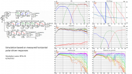
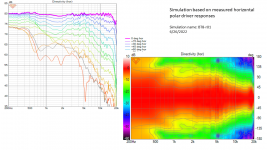
I measured all four drivers near field and far field, according to the VituixCad instructions. The baffle response was simulated for each driver, and the near field response was modified to be 4-pi equivalent. The far field response was made at 39 inches (1 M), on the vertical axis of each driver. Horizontal polar measurements were taken from 0 to 180 degrees in 15 degree increments. Due to symmetry, I made polar measurements to one side only. Vertical polar measurements were not made, in accordance to VCad guidance, so therefore the software will assume the driver vertical response is equal to the horizontal response. The merging of near field and far field was done according to VCad instructions.
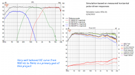
The first three graphics deal with the VituixCad simulation. From a simulation standpoint, I am happy with this filter. It achieves all my objectives, including the key goal for this project which is a well behaved DI curve. The DI is either increasing with frequency, or flat, and it is very smooth from 500 to 5000 Hz. I may develop future DSP filters which optimize other aspects, such as highly consistent horizontal polar responses, assuming it is possible with this baffle layout.
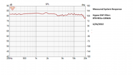
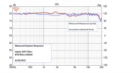
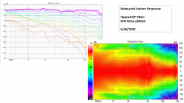
The remaining graphics pertain to measured results. I measured the system in 15 degree horizontal increments. The measured response did not match the simulation as well as I was expecting. My prior projects have had a better match between measurement and simulation. I am not sure why this system is different. I had to adjust the Q of both the mid low-pass and tweeter high-pass filters. I also had to add some additional delay on the tweeter beyond what the VCad simulation predicted. The response I am showing in graphics 4, 5, and 6 is the tweaked DSP filter. Even after tweaking, there is still some improvement to be made.
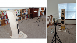
When I am satisfied with the DSP filter, I will make vertical polar measurements. I only want to do this once. My original plan for supporting the 70 lb speaker horizontally is not workable, so I am going to build a roller table.
Another task before me is to take the speaker outdoors and do a ground plane measurement. I have the levels between the woofer and mid approximately correct, but the outdoor ground plane response will allow me to dial it in.
Oh, and so far, it sound pretty good ............ Jim
I measured all four drivers near field and far field, according to the VituixCad instructions. The baffle response was simulated for each driver, and the near field response was modified to be 4-pi equivalent. The far field response was made at 39 inches (1 M), on the vertical axis of each driver. Horizontal polar measurements were taken from 0 to 180 degrees in 15 degree increments. Due to symmetry, I made polar measurements to one side only. Vertical polar measurements were not made, in accordance to VCad guidance, so therefore the software will assume the driver vertical response is equal to the horizontal response. The merging of near field and far field was done according to VCad instructions.
The first three graphics deal with the VituixCad simulation. From a simulation standpoint, I am happy with this filter. It achieves all my objectives, including the key goal for this project which is a well behaved DI curve. The DI is either increasing with frequency, or flat, and it is very smooth from 500 to 5000 Hz. I may develop future DSP filters which optimize other aspects, such as highly consistent horizontal polar responses, assuming it is possible with this baffle layout.
The remaining graphics pertain to measured results. I measured the system in 15 degree horizontal increments. The measured response did not match the simulation as well as I was expecting. My prior projects have had a better match between measurement and simulation. I am not sure why this system is different. I had to adjust the Q of both the mid low-pass and tweeter high-pass filters. I also had to add some additional delay on the tweeter beyond what the VCad simulation predicted. The response I am showing in graphics 4, 5, and 6 is the tweaked DSP filter. Even after tweaking, there is still some improvement to be made.
When I am satisfied with the DSP filter, I will make vertical polar measurements. I only want to do this once. My original plan for supporting the 70 lb speaker horizontally is not workable, so I am going to build a roller table.
Another task before me is to take the speaker outdoors and do a ground plane measurement. I have the levels between the woofer and mid approximately correct, but the outdoor ground plane response will allow me to dial it in.
Oh, and so far, it sound pretty good ............ Jim
Attachments
Nice results up till now! The measured response to me looks better than the simulated. The latter probably has a little too much energy at 3-4kHz (like so often with 5”-1” combos), but the actual response probably is pretty OK.
What do you mean with the difference between simulation and measured result? Do you mean difference between simulation that was based on the actual measurements and to full system response with implemented crossover that is based on the said simulation? This could happen if there is some error on either measurement, or with DSP implementation....
The measured response did not match the simulation as well as I was expecting. My prior projects have had a better match between measurement and simulation. I am not sure why this system is different. I had to adjust the Q of both the mid low-pass and tweeter high-pass filters. I also had to add some additional delay on the tweeter beyond what the VCad simulation predicted.
...
Just in case a reminder, do you have your actual DSP engine set in VituixCAD options? There is some errors if you simulate with one and implement with the other.
That 3-7kHz dip with on-axis signal is weird one, wonder what makes it. Perhaps there is enough error with missing vertical measurements?
Something is definitely off with the data in the simulation, the mid is not as directional in reality as it appears in the simulation.The remaining graphics pertain to measured results. I measured the system in 15 degree horizontal increments. The measured response did not match the simulation as well as I was expecting. My prior projects have had a better match between measurement and simulation. I am not sure why this system is different.
Looking good @hifijim!! I think it looks crazy good as-is. The GD is amazing. The vert/horz above 3khz is like a coax. Very nice!
You have heard this mid and tweeter in a diff. configuration. Do you like the ways it sounds vs what it was?
..
@hifijim can you post a polar graph from just the tweeter? It would be interesting to see if the polar changes because of the mid/XO. Or maybe it is just making the on-axis flat that is making the tweeter a little hot off-axis.
...
You have heard this mid and tweeter in a diff. configuration. Do you like the ways it sounds vs what it was?
..
The mid is playing lots of that.That 3-7kHz dip with on-axis signal is weird one, wonder what makes it. Perhaps there is enough error with missing vertical measurements?
@hifijim can you post a polar graph from just the tweeter? It would be interesting to see if the polar changes because of the mid/XO. Or maybe it is just making the on-axis flat that is making the tweeter a little hot off-axis.
...
The outer baffles have been attached, and the bevels have been rough cut. I attached some pics with notes
Your speakers looks stunning. Props on your craftsmanship. I need to get back to full size speakers. 4-5 years later and 3 different stand mounts. I gave small designs a fair chance.
@hifijim I have some doubts. Why do we have to prioririze directivity index smoothness at the expense of power response bumps? Is this the best approach with direct radiating tweeters?
What would be more audible, power response smoothness or directivity index smoothness?
i got these doubts seeing the power response bumps around 4-5 kHz in your simulated response
What would be more audible, power response smoothness or directivity index smoothness?
i got these doubts seeing the power response bumps around 4-5 kHz in your simulated response
In my eyes hifijim's measured response looks excellent!
On-axis recession is compensated by off-axis nicely. Verticals Will be more interesting... Group delay is typical for 3-way with sealed bass. LR2 xo would be even better.
On-axis recession is compensated by off-axis nicely. Verticals Will be more interesting... Group delay is typical for 3-way with sealed bass. LR2 xo would be even better.
I agree with Juha,
I know you didn't ask for help Jim, in your last post, but it looks good, and can even be better. 🤣
Try LR2 between MF and HF and you'll get better ER and PR and PIR, whilst maintaining smooth neutral on-axis and LW, as well as better phase integration at the crossover point.
I wouldn't lose sleep over the mismatch between crossover based on simulation, and the crossover based on actual measurements. Just make accurate real measurements including polars, and VituixCad2 will do the rest.
Reference: https://www.erinsaudiocorner.com/loudspeakers/parts_express_copperhead/
Erin's measures this kit with his Klippel NFS, then takes out the crossover, and measures the drivers, in-box, and then sims the crossover with VituixCad2, and then compares the simulated crossover with the actual speaker with the complete passive crossover:
Last edited:
Thanks for all the comments. I am on a trip right now, so there will be no measurements for a couple of days. However, reviewing my notes this morning I found an error in how I implemented the tweeter delay in the Hypex DSP software. When I implement the error in VituixCad, it creates a response similar to the one I measured in post #167. I am hopeful that this will resolve the issue
I am not aware the Hypex HFD software has a VituixCad option? This would not be the first time I missed something that everyone else seems to be aware of.
Good question, and I share your concern. This whole project is an experiment to see if I like the sound of this kind of speaker (DI optimized) in my room.
I will definitely evaluate 2nd order filters from woofer to mid. It is on my list...
j.
YesWhat do you mean with the difference between simulation and measured result? Do you mean difference between simulation that was based on the actual measurements and to full system response with implemented crossover that is based on the said simulation?
This could happen if there is some error on either measurement, or with DSP implementation.
Just in case a reminder, do you have your actual DSP engine set in VituixCAD options? There is some errors if you simulate with one and implement with the other.
I am not aware the Hypex HFD software has a VituixCad option? This would not be the first time I missed something that everyone else seems to be aware of.
I have some doubts. Why do we have to prioririze directivity index smoothness at the expense of power response bumps? Is this the best approach with direct radiating tweeters?
What would be more audible, power response smoothness or directivity index smoothness?
i got these doubts seeing the power response bumps around 4-5 kHz in your simulated response
Good question, and I share your concern. This whole project is an experiment to see if I like the sound of this kind of speaker (DI optimized) in my room.
I will definitely evaluate 2nd order filters from woofer to mid. It is on my list...
j.
I am not aware the Hypex HFD software has a VituixCad option? This would not be the first time I missed something that everyone else seems to be aware of.
There is no HFD option in VituixCAD for the sole reason, Hypex doesn't want to disclose the formulas (according to Kimmo) But I use myself generic and 96 k to approach quite closely what HFD do
I will definitely evaluate 2nd order filters from woofer to mid. It is on my list...
I'm working myself on a similar project (4 drivers, 3 ways) with Fc around 500 Hz and 3.5 kHz and found also that LR2 for the mid and high works better on simulation for the time being.
I will present my project when I will have the 8 inch drivers...
jcga replied already but yeah on VituixCAD options there is DSP system option which affects how the filters work. If you popup your project in VituixCAD and swap the option to some other the graphs can change a bit.I am not aware the Hypex HFD software has a VituixCad option? This would not be the first time I missed something that everyone else seems to be aware of.
I'm positive you'll find it out what makes the difference, hopefully it is the delay you mention so can get on with it 🙂


- Home
- Loudspeakers
- Multi-Way
- New Project - tower 3-way with twin 8s