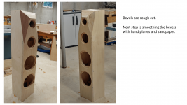
The bliesma was nothing special compared to the others. Waveguides seems to do lots of the difference... But I do not have a waveguide for the bliesma. So more waveguide or not.. rather than bliesma Vs others.digitalthor,
Are you saying that the waveguides worked better (more firm stereo and phantom image) with the Bliesma tweeter vs the SEAS and SB Acoustics tweeters (also with waveguides)?
I clearly prefer waveguides, and the SB26ADC is clearly a little cheap gem 👍
The Bliesma T34 tweeter is one of the best innovations in 104mm faceplate dome tweeters in a long time.
Simultaneously Excellent dispersion and low end extension.
Whether one thinks it’s good value it’s different matter.
Perhaps a waveguide from @augerpro is in the works. We should really make good donations to Brandon - great work!
Simultaneously Excellent dispersion and low end extension.
Whether one thinks it’s good value it’s different matter.
Perhaps a waveguide from @augerpro is in the works. We should really make good donations to Brandon - great work!
I've already tested a couple. Already looking good, so just a couple tweaks were made to new versions. Printing the latest versions right now, and they will likely be put up on my website after that.

try and follow the information presented in this thread with Vituix.
https://www.diyaudio.com/community/threads/vituixcad-simulations-with-ideal-drivers.380658/
If you want more than that the learning curve gets a lot steeper.
Digitalthor - please feel free to post questions about VituixCad simulations in that thread - I found Vcad to be quite easy to use, and the process of making simulations with idealized drivers (flat pistons) is fast. As Fluid mentioned, if we want to get more sophisticated than Vcad, it gets real complicated real fast. Boundary Element Modelling with ATH / AKABAK is the next logical step. I think I will need a ladder to take that next step 🙂
Sorry for going off topic of the thread Jim
No worries, it's all good. Eventually I will add an index in post #1 to all the milestone postings.
j.
A little discussion about bracing...
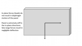
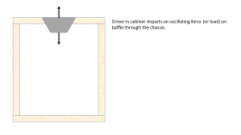
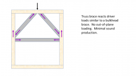
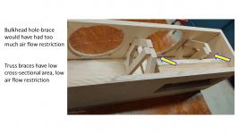
Normally I prefer to use a bulkhead hole-brace above and below each driver. This kind of brace rigidly connects the baffle to the side walls. However, this enclosure is very tall and very narrow. A bulkhead hole-brace with 4 or 5 holes would have had a small open-air area. I prefer the open-air area of a brace to be at least as large as the woofer Sd, and with this very tall very narrow box, that was not possible.
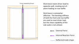
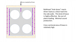
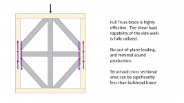
Instead, I used a truss brace. The attached graphics explain why a truss brace achieves the same result as a bulkhead brace, but with a lower cross sectional area.
Normally I prefer to use a bulkhead hole-brace above and below each driver. This kind of brace rigidly connects the baffle to the side walls. However, this enclosure is very tall and very narrow. A bulkhead hole-brace with 4 or 5 holes would have had a small open-air area. I prefer the open-air area of a brace to be at least as large as the woofer Sd, and with this very tall very narrow box, that was not possible.
Instead, I used a truss brace. The attached graphics explain why a truss brace achieves the same result as a bulkhead brace, but with a lower cross sectional area.
Attachments

Just read this. Think it’s ok in general. Two remarks:
- adding corner wood stiffens the junction of the panels and thus the panels themselves. That Is why I would pick the normal approach.
- keeping the openings as large as Sd isn’t necessary. Considering the required volume displacement, air speed ‘through’ a perforated panel isn’t problematic in terms of noise or flow resistance.
I wonder how much percentage of Sd is necessary? 25% is almost certainly not enough... 100% is almost certainly more than enough...I don't know the answer, and I could not find guidance. Since I have two woofers, I decided to play it safe and assume I needed an open-air space equal to the Sd of a single woofer.keeping the openings as large as Sd isn’t necessary.
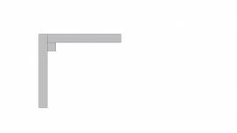
adding corner wood stiffens the junction of the panels and thus the panels themselves.
Adding corner braces (see graphic) will stiffen a un-braced cabinet, I agree with you. An un-braced lightly built cabinet may have separate resonant modes for each wall. Corner bracing can help couple the panels together, and push all four walls to a single resonance mode. This is an improvement. But in a highly braced cabinet with bulkhead or truss bracing, I believe the corner bracing will have little benefit.
Cabinet resonances are difficult to predict with modelling, and difficult to measure. cabinet bracing is a matter of diminishing returns: Simple bracing is a big improvement over no bracing, and the more bracing that is added, the smaller the incremental benefit becomes. Since cabinet resonances are hard to predict, hard to measure, and very hard to fix after construction, I want to be well into the region of diminishing returns. Going "overkill" on bracing adds little cost and little time. And this project is not a high-end build, so I am doing the minimum level of cabinet bracing that I am comfortable with.
In other news, my circle-cutting router is failing. I have been using a small, inexpensive palm router, and routing recesses and full thru cuts in 3/4 inch material has pushed it to its limit. I just bought a new 2 HP Bosch router and am setting up the circle jig with it. I expect to complete the outer baffle in a few days.
j.
Attachments
Having the tools is half of the solution, the Bosch routers are fine, especially the blue ones. Don’t overdo it with big radii, go for incremental cuts and fix your enclosures, even if they are big.
As for percentages, I think 50% would do, as it’s only relevant for the fundamental frequencies and a bit above. Air speeds are very low there. Ports for vented enclosures seldom are more than 25% and 17m/s seems a safe limit, so we could calculate it from there.
As for percentages, I think 50% would do, as it’s only relevant for the fundamental frequencies and a bit above. Air speeds are very low there. Ports for vented enclosures seldom are more than 25% and 17m/s seems a safe limit, so we could calculate it from there.
I want to experiment with that technique before I use it in a real project.I'm curious why you didn't try a simple CLD panel construction though?
With this current project, I am trying some new construction and design ideas, and I did not want to change too many variables... so I stuck with a high-stiffness birch plywood box.
j.
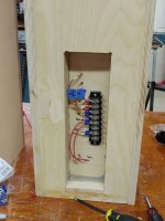
I started wiring the boxes in preparation to install the Hypex FA123 amp, then the drivers. My plan is to do a full set of driver measurements before I start any cosmetic finishing. One reason is that I need a break from woodworking for a while, and the other reason is that I have not decided how I am going to finish these cabinets. I am leaning toward cherry veneer with a satin finish, but I am not sure just yet.
After the driver measurements, I will begin the process of VituixCad simulation to design the DSP crossover.
j.
After the driver measurements, I will begin the process of VituixCad simulation to design the DSP crossover.
j.
Attachments

Fine work hifijim.
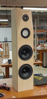
At first glance the distance between mid-range and tweeter catches attention, but the reasons have already been shared by you in post #106 of this thread.
https://www.diyaudio.com/community/...3-way-with-twin-8s.378223/page-6#post-7017084
Look forward to the measurements.
At first glance the distance between mid-range and tweeter catches attention, but the reasons have already been shared by you in post #106 of this thread.
https://www.diyaudio.com/community/...3-way-with-twin-8s.378223/page-6#post-7017084
Look forward to the measurements.
Yes, we all patiently look forward to see the polar response of this fully vertically integrated system. 🥷
Last edited:
Amazing is a big word... I am satisfied with the quality so far, but this project has stretched my wood-working skills. The "system pictures" sticky thread has some photos that put me in awe.... we have some really talented cabinet makers on this forum.Amazing work. Congrats to reaching the all-together-now project level. Cheers!
At first glance the distance between mid-range and tweeter catches attention, but the reasons have already been shared by you in post #106 of this thread.
Yeah I am curious to see how this sounds. It sure looks odd, but it simulates well.
j.
I second that. Amazing work! I could not make that. My only woodworking skill is eating popsicles.Amazing work. Congrats to reaching the all-together-now project level. Cheers!
Good luck with the measurement portion. Hopefully, things fall where you expect.
Digitalthor - please feel free to post questions about VituixCad simulations in that thread - I found Vcad to be quite easy to use, and the process of making simulations with idealized drivers (flat pistons) is fast. As Fluid mentioned, if we want to get more sophisticated than Vcad, it gets real complicated real fast. Boundary Element Modelling with ATH / AKABAK is the next logical step. I think I will need a ladder to take that next step 🙂
Very interesting speaker project and almost exactly the one I was arguing for in the collaborative open source project thread/s. I have an interest in possible next steps.
Simulating the 3D acoustical field with BEM (or equivalent) would enable one to answer questions concerning the details of waveguide geometries, optimising the baffle shape around the tweeter and perhaps midrange, radiating patterns of the cabinet modes, and perhaps one or two other things. If the simulation includes absorption then more could be studied and particularly how the speaker may sound in various rooms via auralization but that would involve some hardware and measurement as well as the simulation to be successful. Loudspeaker in a room auralization almost certainly needs that ladder today but much of the other stuff is being performed by DIYers today.
Would the quality of the decisions concerning the stiffness and damping of the cabinet structure have been raised by using FE structural analysis? Freely available software is around and some of it isn't that difficult to use if one is familiar with performing structural analysis or keen to learn. The biggest issue I have found is that the freely available damping models are too basic/simplistic to efficiently simulate viscoelastic materials of the kind one would use in a high quality speaker cabinet. One can still answer a lot of questions and get complete results at a few discrete frequencies just not a full FRF efficiently obtained via some form of modal analysis when viscoelastic damping is involved.
CFD/CAA is perhaps the most complicated and least useful of the 3D simulation tools that could be used to help design a DIY speaker by studying the air flow within the cabinet, through the port and outside near the speaker. Ladder required but suitable freely available research software is available for those that might be keen.
- Home
- Loudspeakers
- Multi-Way
- New Project - tower 3-way with twin 8s