The reason for this is not because I am a good designer, but because I followed Kimmo/VituixCAD's directions and took real measurements in 360 degrees BEFORE I started the crossover.
And before that I also simulated the baffle dimensions and driver positioning with VituixCAD diffraction modeller.
Yes for sure the way to go, real measurements in real results out and yours looks better than most.
Simulations with ideal drivers, or with anything really, are great help for learning. Most of the time I'm not simulating any particular speaker, just using VituixCAD or Ripple tank or just imagination ( ;D ) as a tool to figure out stuff, what would make better measurements as those are the real limit for performance. Crossover part is trivial now that we have VituixCAD but one has to know something about crossover to avoid bad options and then build a construct that measures well. Or well enough so that one can just straighten the rest up with crossover, EQ. The system needs to work together acoustically, this is what we listen to, in a room. Drivers are also kind of trivial, just use good ones that fit the purpose, can be more or less expensive. Even the ideal drivers don't make nice system as seen above in this simple example, unless the system is thought out and then almost any correct size driver that is not particularly poor makes nice measurements. Very high tech speakers require special drivers to reach targets. For example the purifi woofers are really good for small two way speakers, more SPL capability from small packet size. More SPL capability can be reached also by using bigger system, bigger/more drivers. Well, preaching to the choir I guess 😀
Last edited:
Tktran - I could not find a thread with a description of your speaker, although I am sure I remember reading about it at some point...
Perhaps true. Maybe the lost the mojo... It is also possible that their speakers have a signature sound, and it sells well. If something is selling well, it may be risky to "improve" it. If B&W engineered their 800 series speakers to sound like a Revel Salon (which has excellent on-off axis response), well, it might just sound like a Revel Salon... and perhaps B&W customers don't want that...
B&W's engineers are clever enough but my guess it that
a) they want to make the most of their soft cone FST, which admittedly extends out to 10KHz
b) they are probably using old processes, old tools.
Perhaps true. Maybe the lost the mojo... It is also possible that their speakers have a signature sound, and it sells well. If something is selling well, it may be risky to "improve" it. If B&W engineered their 800 series speakers to sound like a Revel Salon (which has excellent on-off axis response), well, it might just sound like a Revel Salon... and perhaps B&W customers don't want that...
I let this project sit idle for a couple of weeks while I did some house projects and then did some vacation travel.
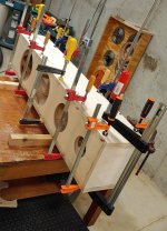
I have glued on the side panel, which was the last remaining panel of the main carcass. The main carcass is now done. All internal bracing is installed. The next step will be to construct the outer baffle and glue it on.
I have glued on the side panel, which was the last remaining panel of the main carcass. The main carcass is now done. All internal bracing is installed. The next step will be to construct the outer baffle and glue it on.
Attachments

Tktran - I could not find a thread with a description of your speaker, although I am sure I remember reading about it at some point...
Perhaps true. Maybe the lost the mojo... It is also possible that their speakers have a signature sound, and it sells well. If something is selling well, it may be risky to "improve" it. If B&W engineered their 800 series speakers to sound like a Revel Salon (which has excellent on-off axis response), well, it might just sound like a Revel Salon... and perhaps B&W customers don't want that...
Jim,
this speaker was the 3 way example project in the “how to design a speaker using measurements” thread:
https://www.diyaudio.com/community/threads/how-to-design-a-speaker-using-measurements.385687/
but I haven’t got around to making dedicated thread about it yet, mainly due to indecision about the best modality of teaching/learning in C21 (pedagogy).
I firmly believe that written and visual aids are the basics (books/forums etc) but video and audio is of great benefit when explaining topics.
For instance here are some static pictures that may be understood by yourself but for others at a different stage of their journey, really deserve their own chapter/thread/video series.
So it hasn’t been documented.
ive used a few photos in a variety of posts as a counter-example to some commonly held beliefs; or to accentuate the strengthsreinforce what can be a achieved with baffle simulations, or what can be achieved when you don’t have the ability or resources to do faceted/large round over cabinets etc.
PS. Let me know if you want me to remove these on your thread; happy to do so.
PPS. As for the B&W flavour of sound; yes perhaps. Every designer has their own goals/philosophy/vision etc.
Many years ago when Laurence Dickie was still at B&W I heard the big 800 series in large acoustically treated home theatre/custom install room and on axis they are VERY good. and so we can criticise B&W all we want; but they are the ones earning a living from their designs; so something is working.
Attachments
Last edited:
Even the ideal drivers don't make nice system as seen above in this simple example, unless the system is thought out and then almost any correct size driver that is not particularly poor makes nice measurements. Very high tech speakers require special drivers to reach targets. For example the purifi woofers are really good for small two way speakers, more SPL capability from small packet size. More SPL capability can be reached also by using bigger system, bigger/more drivers. Well, preaching to the choir I guess 😀
yes; it’s like that 20th century advice: choose well behaved eg. polypropylene drivers so that it makes life easier for you.
Good drivers make it easier.
DSP makes it easier.
it makes you think you are a good designer, right?
Any DIYer can spend an unlimited budget and unlimited time and wind up the EQ until one starts dancing. Now course one still has to have a handle on the foundations. Acoustics, physics etc.
What’s really hard, is to doing more, with less.
Or knowing what matters the most.
I really respect those guys like Andrew Jones, Jack Hidley, Dennis Murphy, Wolf etc…
But for sure you gotta listen, measure, listen, measure; measure listen; measured listen…
Attachments
Last edited:
Here are a few other nit-nats that may be interesting...
Every project should have a goal, or objective, or statement of purpose, right? Since this project has changed quite a bit since it started last October, I thought I should clarify the goals.
Goals for this project
1) Design and build a complex 3 way system using VituixCad simulation from the start.
2) Build and evaluate a system with optimized DI and a smooth even horizontal dispersion.
3) Explore some new cabinet construction ideas.
4) Have a system which is more portable than my existing system.
5) Have a system which can serve as a backup for my main system.
Acoustical absorption (stuffing)
This is a sealed box system, and the midrange enclosure is also sealed. I have had good results with long fiber wool stuffing, so that is what I am using here as well. I will start at a density of 1 lb/ft^3, which is about 16 g/liter. I will use both impedance sweeps and nearfield measurements of the woofers and midrange to assess if I have enough acoustical damping. I bought a 5 lb box of long fiber natural wool stuffing from Mountain Meadow Wool in Wyoming. This is enough for this project and at least one future project.
Does normalize mean, that you perfectly flatten the on-axis in the simulation, so that you get the "pure" difference between on and off axis? Which again means, that normalizing a real measurement, would kinda confuse how the speaker actually measures?Played with VituixCAD and it can do close the same graphs as the Stereophile normalized horizontal graphs are. Attached is a VituixCAD project that can produce the images below. I urge anyone play with it to gain some insight how the speaker construct relates to various things on the graphs.
Here is ideal point source, this is the best that can be, straight lines. This is omni and all off-axis angles have same level. If it was narrower directivity but still constant directivity, the lines to off-axis angles were just lower in level but still straight.
View attachment 1058592
Below responses are ideal 1" and 8" transducers on ~minimal 20x40cm baffle made with VituixCAD diffraction tool.
Here is only the tweeter with and without 25mm corner radius on baffle. Response is about omni on low frequencies until baffle starts to narrow it, eventually the transducer beams as wavelengths get shorter than the diameter. Diffraction in between which almost cleans out with 25mm radius roundover on the baffle edge. The baffle is quite large for the tweeter and roundovers are needed to reduce diffraction.
View attachment 1058593View attachment 1058594
This is ideal 8" woofer on the same baffle without and with 25mm roundovers. Its minimal baffle for the woofer so not much effect to its response.
View attachment 1058595View attachment 1058596
And here is the system with 3kHz LR12 crossover, with and without the roundovers:
View attachment 1058599View attachment 1058600
Yes its not too good of a system, 8" and 1" with 3kHz crossover, just something arbitrary to give more data whats what on the graphs.
Is there anything to learn? Yeah, do roundovers (and EQ) if you wanna make your graphs look better than in Stereophile! Pay attention to driver sizes and locations, structure, the construct.
Note the graphs are Normalized to on-axis, meaning that the on-axis response is "EQd" perfectly flat to show off-axis angles response in comparison to that. Perhaps Juhazi observed from the graphs he linked on post #113 the B&W really has kind of wild on-axis response and came to conclusion minimal baffle didn't help. The ragged response is not due to diffraction though, except some on the tweeter but less than with the others, and could be EQ:d pretty nicely.
Here is simulation with real system measurements. Its not normalized but just EQ:d quite flat, the construct is made low diffraction without roundovers, basically its no baffle cardiodish with freestanding waveguide. Wouldn't be so nice without help of DSP, would have ragged on-axis response but normalized graph would look about the same as this. Btw there is two crossovers here, its a three way system.
View attachment 1058606
You can normalize to any axis but most often it is the on axis. It is done by dividing all the other curves by the normalizing curve. Dividing something by itself gives the flat line.Does normalize mean, that you perfectly flatten the on-axis in the simulation, so that you get the "pure" difference between on and off axis? Which again means, that normalizing a real measurement, would kinda confuse how the speaker actually measures?
It is a reasonable representation of what could be done if that axis was flattened by EQ, and will highlight how well the directivity might react to EQ.
Normalizing doesn't confuse anything as long as you understand what has been done and what it means.
Yeah exactly. It could be argued that on axis response should be flat for best sound quality for any loudspeaker in which case a normalized graphs like these kind of show the very best case response the system is capable of. This is great information for speaker designer.
For example the ripple due to diffraction is there no matter the EQ. Could be filtered out by low passing the diffracting driver on a multiway speaker below the diffraction happens, but in case of a tweeter we cant do it because we want it to play all the way to top. Only way to get rid of the ripple is to make better physical construct, that simply performs better acoustically and doesn't create (as much) these issues on the graphs.
As always this would affect cost and aesthetics so perhaps it is not too important for anyone doing DIY or doing commercial products with set budget and industrial design. For example if distortion performance, on axis performance, SPL and bandwidth capability is not top notch then perhaps some diffraction doesn't matter. On the other hand if all else is already taken care off then its logical try and tackle some of these issues as well.
Not in all cases though. It also depends what is meant by on axis, as when the speaker is toed in or out that direct axis to the listener can change. If a horn or waveguide is used then most often 10 to 20 degrees off axis horizontally will be the preferred listening axis. If the DI is flat and not rising then flat on axis is almost always too bright.Yeah exactly. It could be argued that on axis response should be flat for best sound quality for any loudspeaker in which case a normalized graphs like these kind of show the very best case response the system is capable of. This is great information for speaker designer.
Also you must avoid normalizing horizontal and vertical axes to different values (other than as an evaluation tool) as that will be impossible to replicate in real life.
Yeah for most design and simulation purposes it is listening / reference / design axis that should be the target to use, not on-axis if its not the intended listening axis.
However inspecting if diffraction or any other interference related ripple exists due to construct it doesn't matter too much which axis to normalize because the response varies to every direction the output can be smooth only to one axis and others remain more or less ragged no matter which axis is normalized, or "EQd".
Here are previous example normalized to 0, 10, 20, 30 and 40 deg off axis.


This is just one special case, or point of view, how the simulator and data can be utilized, to evaluate if the construct is good or perhaps if it could be bettered somehow to measure better, what ever that means for given system. This point of view is not directly to make crossover but indirectly, after the fact, as the crossover and the resulting performance is pretty much dictated by the construct we cannot "correct" much any of this in the simulation or in crossover filters so we just have to build better construct, measure again, evaluate again etc 🙂 At least some of it can be evaluated without building anything, by simulation. Anyway, not for all projects, but if one intends to build multiple projects or do lots of prototyping for fun perhaps then its useful design process to get better performance, what ever that is.
However inspecting if diffraction or any other interference related ripple exists due to construct it doesn't matter too much which axis to normalize because the response varies to every direction the output can be smooth only to one axis and others remain more or less ragged no matter which axis is normalized, or "EQd".
Here are previous example normalized to 0, 10, 20, 30 and 40 deg off axis.
This is just one special case, or point of view, how the simulator and data can be utilized, to evaluate if the construct is good or perhaps if it could be bettered somehow to measure better, what ever that means for given system. This point of view is not directly to make crossover but indirectly, after the fact, as the crossover and the resulting performance is pretty much dictated by the construct we cannot "correct" much any of this in the simulation or in crossover filters so we just have to build better construct, measure again, evaluate again etc 🙂 At least some of it can be evaluated without building anything, by simulation. Anyway, not for all projects, but if one intends to build multiple projects or do lots of prototyping for fun perhaps then its useful design process to get better performance, what ever that is.
Last edited:
Ok... thank you. Who would'n want a pretty flat on-axis, and if the off-axis is not.... then the overall design is surely wrong?You can normalize to any axis but most often it is the on axis. It is done by dividing all the other curves by the normalizing curve. Dividing something by itself gives the flat line.
It is a reasonable representation of what could be done if that axis was flattened by EQ, and will highlight how well the directivity might react to EQ.
Normalizing doesn't confuse anything as long as you understand what has been done and what it means.
I never made a simulation in my life, would like to know how though, but only tried a few times, but gave up for now, since I could just copy others and simply build test boxes and measure the real thing, and then learn the hard way, why drivers with a certain size act the way they do at a given distance to a given size cabinet and neighboring driver.
Is there some software, where you can just put in 2 circles in a square, representing a tweeter and midrange in a baffle, and then fiddle with the numbers, to see what happens... or maybe a premade example, also with slanted/edged baffle?
If for me... then yes... I think that software kinda gives me an idea... which already make sense from how a minimal baffle and raw driver FR work together. I was thinking of more advanced versions...You mean The Edge maybe?
Try and follow the information presented in this thread with Vituix.I was thinking of more advanced versions...
https://www.diyaudio.com/community/threads/vituixcad-simulations-with-ideal-drivers.380658/
If you want more than that the learning curve gets a lot steeper.
Close to flat is usually ideal, but if the DI is flat having the on axis also flat ends up being bright. Not wrong just different.Ok... thank you. Who would'n want a pretty flat on-axis, and if the off-axis is not.... then the overall design is surely wrong?
What the term on axis means is also not always clear. Some may mean it to be zero straight ahead, but if the speaker was designed on a different reference axis that axis is really the "on axis" when listened to.
Thank you - I'll try that 👍Try and follow the information presented in this thread with Vituix.
https://www.diyaudio.com/community/threads/vituixcad-simulations-with-ideal-drivers.380658/
If you want more than that the learning curve gets a lot steeper.
I only use a small waveguide ( 5" Augerpro with SB26ADC ) so the DI can't be flat due to natural high end frequency room absorption, and the falling characteristics off the waveguides off-axis response. My measurements at the listening position confirms that I have smooth falling trend in the FR, which is the "ideal" - with the speaker tuned to be flat on-axis - dead ahead, in between the midrange and tweeter - at listening height.Close to flat is usually ideal, but if the DI is flat having the on axis also flat ends up being bright. Not wrong just different.
What the term on axis means is also not always clear. Some may mean it to be zero straight ahead, but if the speaker was designed on a different reference axis that axis is really the "on axis" when listened to.
I found this approach to be like a mix between all the inspiration I could find, between - to my opinion - good sounding speakers and all the ideas from Geddes, Toole and Olive. Also - in general, just use drivers, that can work easily within their pass band.
This seems to be a common misconception but the directivity of a speaker and corresponding DI is an anechoic quantity. High frequency absorption in room isn't the reason for the slope. The DI of a waveguide that size could absolutely be flat but that would be pointless unless it was crossed to other waveguides that had a similar directivity. It is the shape of the wall that determines the directivity until the physical size of the driver becomes a limit unless a slot of some kind is used.I only use a small waveguide ( 5" Augerpro with SB26ADC ) so the DI can't be flat due to natural high end frequency room absorption, and the falling characteristics off the waveguides off-axis response.
A smooth constantly falling in room response is the result of a speaker with a smooth constantly rising directivity index. For cone and dome speakers including ones with small waveguides this is a good target. Ideal would be a step too far as there are other ways to get equally good sound with different directivities. For example KEF's newer speakers where the directivity is quite flat and the D&D 8c. True dipoles have flat DI and tend to need a downslope to the on axis to sound right.My measurements at the listening position confirms that I have smooth falling trend in the FR, which is the "ideal" - with the speaker tuned to be flat on-axis - dead ahead, in between the midrange and tweeter - at listening height.
Nice... several things I have thought about, already knew and also experienced, fell into place there - thank you 😀This seems to be a common misconception but the directivity of a speaker and corresponding DI is an anechoic quantity. High frequency absorption in room isn't the reason for the slope. The DI of a waveguide that size could absolutely be flat but that would be pointless unless it was crossed to other waveguides that had a similar directivity. It is the shape of the wall that determines the directivity until the physical size of the driver becomes a limit unless a slot of some kind is used.
One of my friends has a Bliesma tweeter, which are obviously WAY more expensive than my Seas DXT and SB26ADC. But when we setup an experiment, where we could quickly shift between different drivers, by having them in small "building block" sized cabinets ( midranges too). We could very quickly hear that any type of waveguide, clearly create a much more "firm" stereo and phantom image, than the freely radiating Bliesma tweeter. Maybe... just maybe... the Bliesma in a waveguide, could play, somehow better - at least in theory. But for me, I need more proof, to use that kind of money 😊A smooth constantly falling in room response is the result of a speaker with a smooth constantly rising directivity index. For cone and dome speakers including ones with small waveguides this is a good target. Ideal would be a step too far as there are other ways to get equally good sound with different directivities. For example KEF's newer speakers where the directivity is quite flat and the D&D 8c. True dipoles have flat DI and tend to need a downslope to the on axis to sound right.
- Home
- Loudspeakers
- Multi-Way
- New Project - tower 3-way with twin 8s